7 Electrical wiring
Electrical wiring diagram
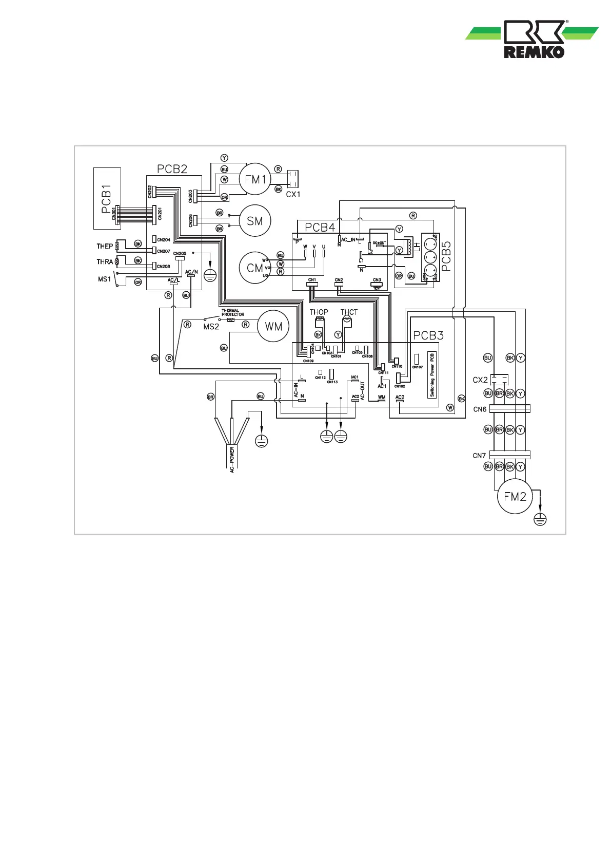
Fig. 17: Electrical wiring diagram
PCB1: Keypad board
PCB2: Control board
PCB3: Motherboard
PCB4: IPM protection board
PCB5: Capacitor board
CM: Compressor
CX1: Capacitor, evaporator fan
CX2: Capacitor, condenser fan
FM1: Evaporator fan
FM2: Condenser fan
LH: Reactor
MS1: Microswitch malfunction, (container
full)
MS2: Microswitch condensate pump
SM: Swing motor
THCT: Compressor temperature probe
THEP: Probe, evaporator
THOP: Compressor end temperature probe
THRA: Room temperature probe
WM: Condensate pump
Colour coding:
BK: black
BR: brown
BU: blue
GR: grey
OR: orange
R: red
W: white
Y: yellow
17
 Loading...