Outdoor unit RVT 682 AT
NO
NC
COM
L-OUT
RY2
GND
P-1
CN 4
N-
IN
L –IN
CN3
P1
P2
FUSF1
T5A 250VAC
CN 1
CN 8
CN 6
CN 9
CN 5
CN 2
SW 1
CN 26
CN 7
CN 17
CN 21
CN 39
CN 37
CN 29
DSP1
CE-KFR80W/BP3T4N1(DC MOTOR)-310.D.03.WP1-1
202302130895
X
CN 38
CN 10
202302130890
CE-KFR80W/BP2T4N1-310(B):D:13:MP1
CN8
LED1
LED2
CN10
CN7
CN9
CN6
CN1
CN11
CN12
CN2
CN4
CN5
CN3
1
CN4
A
B
2
3
4
5
6
7 8
9
10
11
13
14
15
17
18
19
11
16
20
12
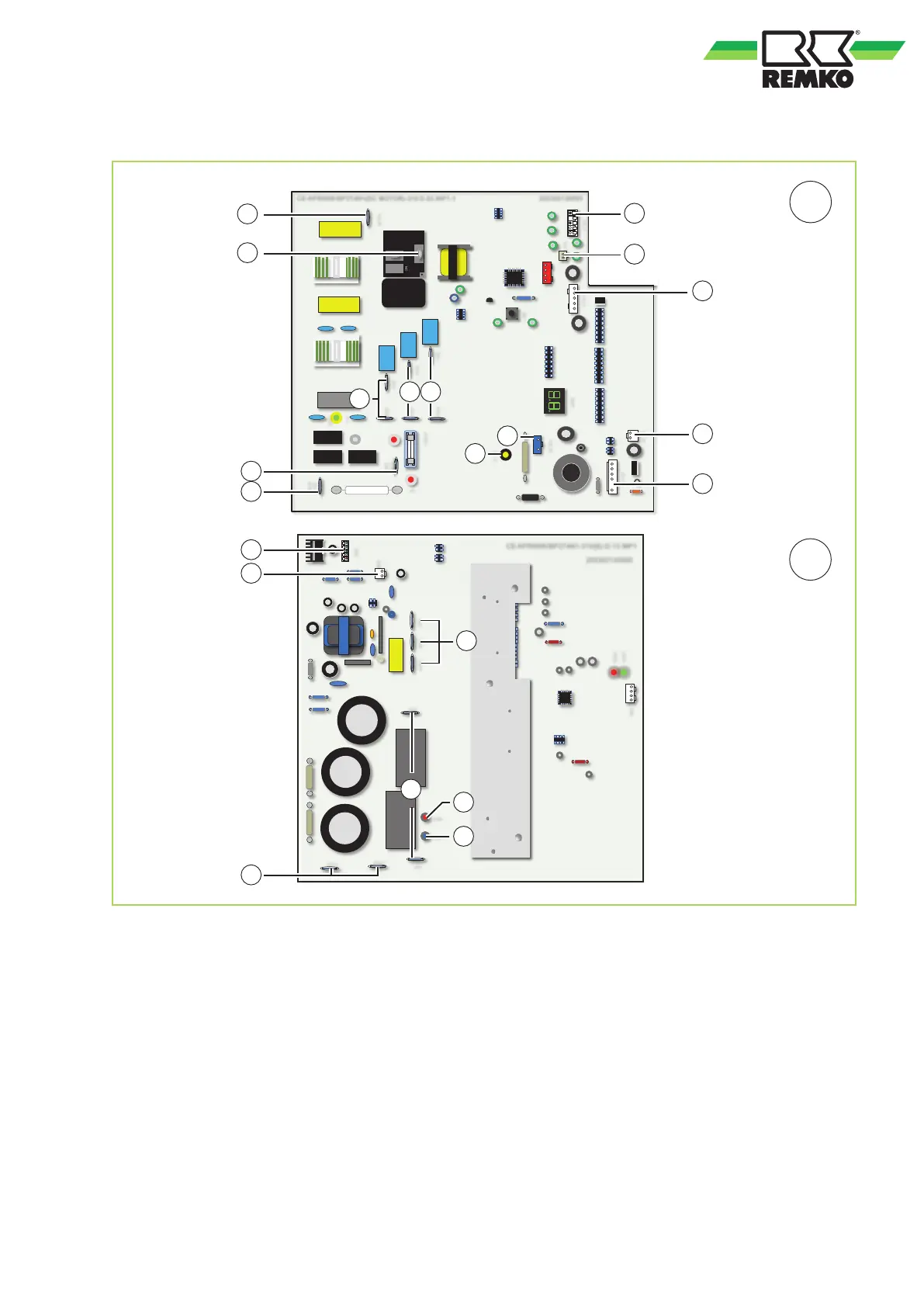
Fig. 53: Electrical drawings
A: Main board
B: Inverter board
1: Connection to the inverter board (contact CN 4)
2: Connection to the inverter board (contact CN 5)
3: Outside air probe, condenser probe
4: Heat gas probe
5: Connection to the inverter board (contact CN 1)
6: Condensate tray heating
7: Crankcase heating
8: 4-way valve
9: Connection to the inverter board (cont. CN 6)
10: Reactor
11: Connection to the inverter board
(contacts CN 11, CN 12)
12: Control line indoor unit (yellow), contact S
13: Supply indoor unit (red), contact L, (L1)
14: Supply indoor unit (black), contact N, (L2)
15: Connection to the main board (contact CN 21)
16: Connection to the main board (contact CN 38)
17: Connection to the main board (contact CN 39)
18: Connection to the main board
(contact NO-OUT)
19: Connection to the main board
(contact RY2 COM)
20: Compressor
45