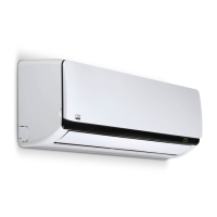
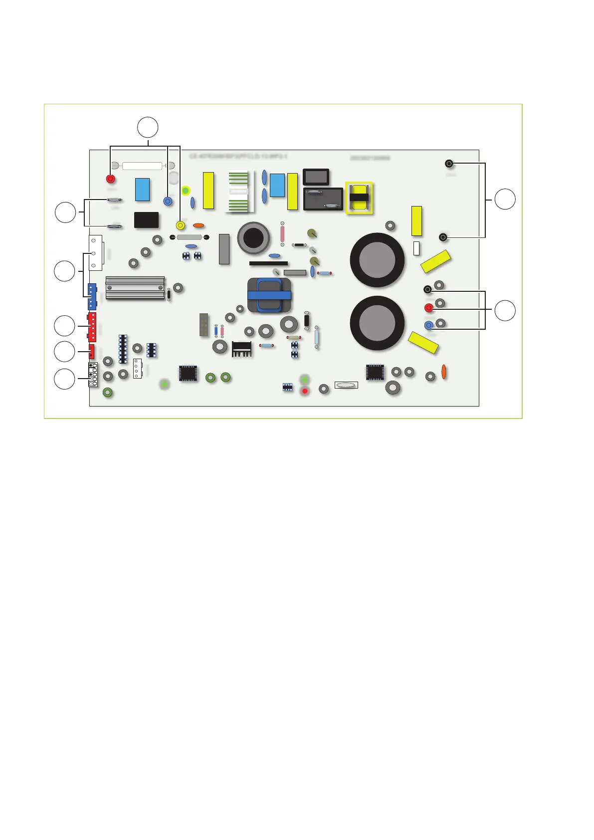
Outdoor units RVT 262 AT, RVT 352 AT und RVT 522 AT
X
CN302
CN303
CN8
CN10
CN11
CN301
CN13
CN12
CN15
3
4
CN401
CN400
CN9
CN104
CN103
CN102
CN100
CE-KFR26W/BP3(PFC).D.13.WP2-1 202302130906
2
1
4
3
5
6
7
A
Fig. 52: Electrical drawingsRVT 262 AT, RVT 352 AT und RVT 522 AT
A: Supply to the indoor unit
CN 12 = Terminal block indoor unit / contact N
CN 13 = Terminal block indoor unit / contact L
CN 15 = Terminal block indoor unit / contact S
1: Outside air probe, condenser probe
2: Heat gas probe
3: Injection valve
4: Condenser fan
5: 4-way valve
6: Reactor
7: Compressor
REMKO RVT-ARCTIC-WP
44