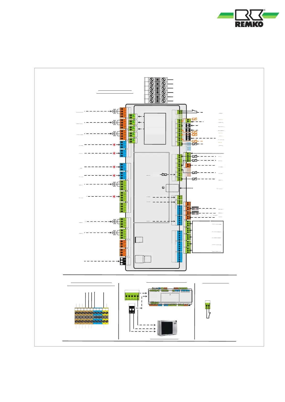
3.5 Electrical configuration - I/O module 01 - WKF 130/170 Duo
Use wire gauge corresponding with the connection cable supplied!
Lay load lines separately to measuring lines!
EP/N/~1/V032 :ssulhcsnA
PE N L
PE N L`
PE N L`
PE N A10 L`
PE N A1
1 L`
PE N A12 L`
PE N A13 L`
PE N A14 L`
PE N A01
PE N A02
PE N A03
PE N A04
PE N A20 A21
Power
Actuator Outputs
Actuator Supply
Actuator Outputs
Actuator Outputs
stupnI
rosneS
S25 +5V GND
S26 +5V GND
S27 +5V GND
S28 +5V GND
S29 +5V GND
langiS rotautkA
GND A40
GND A41
GND A42
GND A43
GND A44
GND A45
GND A46
MI MO CLK nSS GND
PT -
NK
X
0T1 0T1
0T2 0T2
B2 A2
+12V B1
A1 GND
S20 +5V GND S40 S41
S21 +5V GND S42 S43
S22 +5V GND S44 S45
S23 +5V GND S46 S47
S24 +5V GND S48 S49
S01 GND
S02 GND
stupnI rosneS
S03 GND
S04 GND
S05 GND
S06 GND
S07 GND
S08 GND
stupnI rosneS
S09 GND
S10 GND
S11 GND
S12 GND
Potential Free Outputs
A30 A30
A31
SD
Fuse
RJ 45
LR sierkzieH rethcsimeg .1
LV sierkzieH rethcsimeg .1
rutarepmetneßuA
ettim rehciepS
M
Zu
Auf
sierkzieH rethcsimeg .1
V 032 epmuP
ludoM O/I gnugrosrevsgnunnapS
sierkzieH rethcsimeg .1
V 032 rehcsiM
M
litnevtlahcsmU
reguezreemräW 2
V032 raloS epmuP
ungeregelt
epmupsnoitalukriZ
W ) V 032 ( ressawmra
LV sierkzieH rethcsimeg .2
LR raloS
MWP ebagrovlhazherD
epmupraloS
gnusiepsniE VP 0S
hWk/.pmI 005 .nim(
gartrE VP 0S
hWk/.pmI 005 .nim(
relhäzstlahsuaH 0S
hWk/.pmI 005 .nim(
PW 0S relhäzmortS
hWk/.pmI 005 .nim(
Sensor
Inputs
Sensor
Inputs
rotkelloK-raloS
netnu rehciepS-raloS
DNG/92S
DNG/82S
S26/GND
S25/GND
S23
10S
S02
S03
S04
S06
S09
S10
S11
S12
A40
A13
A01
A02
A04
22/12A
V raloS mortsnemulo
A42
A41
MWP / V01-0 epmuP
sierkzieH rethcsimeg .2
A46
T-lortnoCtramS gnugrosrevsgnunnapS ouch
B1/A1
noitakinummoK ludomneßuA
B2/A2
V032 epmuP
sierkzieH rethcsimeg .2
A11
V W mortsnemulo ressawmra
DNG/72S
O/I TMS
sierkzieH rethcsimegnu
) lanoitpo ( V 032 epmuP
A03
M
/litnevtlahcsmU
nelhüK epmuP
A14
M
litnevtlahcsmU
W gnutierebressawmra
A10
PE N A22 A23
PE N A24 A25
C
R
B3 A3
R GND
S13 GND
S14 GND
S15 GND
S16 GND
A32
A33
A34
tkatnoK UVE
ebagierF = nessolhcseg
M
V 032 litnevssapyB
M
sierkzieH rethcsimeg .2
V 032 rehcsiM
EW 2 / ebagierF 23A
lemmaS 43A
gnudlemrötS
ierflaiznetoP
LR sierkzieH rethcsimeg .2
S14
S16
32/22A
52/42A
ztühcsrrepS enho :SIEWNIH
nedrew tgelegnie ekcürB ssum
dnatsrediwreidoC
RC.1
V21+ & DNG emmelK
MWP /V 01 - 0 epmuP
sierkzieH rethcsimegnu
MWP / V 01 - 0 epmuP
sierkzieH rethcsimeg .1
Zu
Auf
Zu
Auf
LV relhüfraloS
S05
noitalukriZ
T slupmI redo rutarepme
W relhüF ressawmra
S08
(2.)
(1.)
rosnesmuaR noitakinummoK
B3/A3
T-lortnoCtramS noitakinumoK ouch
RJ 45
DNG SSn KLC OM IM
2B 2A
(3.)
(1.)
I/O Modul noitakinummoK ssulhcsnA
etsielnemmelK ludomneßuA
s
tuptu
O
ee
rF
la
i
t
n
etoP
I/O Modul
gnulietrevretnU red sua stiesuab
tglofre gnugrosrevsgnunnapS ludoM O/I
(3.)
DNG 61S
(2.)
ebagierF = nessolhcseG
!ierflaitnetoP :tkatnoK
61S tkatnoK UVE
tkatnoK UVE ssulhcsnA
EP/N/~1/V032 :ssulhcsnA
gnulietrevretnU red sua stiesuab
tglofre gnugrosrevsgnunnapS ludoM-O/I
GND
N
L1
N
L1
L1
)EP/N/~3/V004
gnulietrevretnU red sua stiesuab
vreS tramS tnemelezieH .kele gnugrosrevsgnunnapS
3x 230V/1~/N/PE
dann Brücken N-Leiter entfernen
EP
N
N
L1
L2
L3
EP
N
L1
L2
L3
B
e
l
e
g
t
B
e
l
e
g
t
B
e
l
e
g
t
B
e
l
e
g
t
S
T
B
E
-
H
e
i
z
u
n
g
Re
l
a
i
s
E
-
H
e
iz
.
Be
l
e
g
t
E
-
H
e
i
z
u
n
g
GND
PE
N
ebagierF 33A
1 efutS vreS tramS
2 efutS vreS tramS
B
e
l
e
g
t
B
e
l
e
g
t
Assigned
Assigned
NOTE: without blocking
contactor, jumper must be
inserted, closed = enabled
Power utility contact
2nd mixed heating cycle RF
Coding resistor
Room sensor communication
Outdoor unit communication
Storage tank, centre
Terminal GND & +12V
Hot water probe
2nd mixed heating cycle
Temperature or impulse
Pump 0-10V / PWM
Circulation
Solar probe inlet
Smart Control Touch communication
1st mixed heating cycle INL
1st mixed heating cycle RF
Outside temperature
2nd mixed heating cycle INL
Smart Control Touch power supply
Unmixed heating
1st mixed heating cycle
Solar pump
Pump 0 - 10 V/PWM
S0 PV feed-in
(min. 500 lmp./kWh)
S0 PV yield
(min. 500 lmp./kWh)
S0 household meter
(min. 500 lmp./kWh)
S0 HP electricity meter
(min. 500 lmp./kWh)
Hot water medium ow rate
Pump 0 - 10 V/PWM
Speed setting PWM
EVU contact connection
I/O module: Communication connection
Elec. power supply Smart Serv heating element
provided by the customer from the sub-distribution unit
Terminal block outdoor unit
Assigned
Power utility contact S16
Closed = enable
Contact: Potential-free!
Assigned
Assigned
STB
assigned
Assigned
Electrical
heater
Electrical
heater
Electric
heater relay
3x 230V/1~/N/PE
then remove N-conductor jumpers
2nd mixed heating cycle
Potential-free
A34 General alarm
code
A32 enable/2 HG
Smart Serv stage 2
1st mixed heating cycle
Pump 230 V
Changeover valve /
Changeover valve
Changeover valve
Bypass valve 230 V
230 V mixing valve
Closed
Closed
Closed
230 V mixing valve
Pump 230 V
Unregulated
2nd mixed heating cycle
pump cooling
2 heat generators
Hot water preparation
Power supply I/O module
Solar RF
Solar storage tank, bottom
Solar collector
Medium ow rate solar
Hot water (230 V)
Pump 230 V (optional)
A32 enable
Smart Serv stage 1
Pump solar 230 V
1st mixed heating cycle
Unmixed heating cycle
Circulation pump
Open
Open
Open
I/O module: Power supply provided by
the customer from the sub-distribution unit
Connection: 230V/1~/N/PE
33

 Loading...