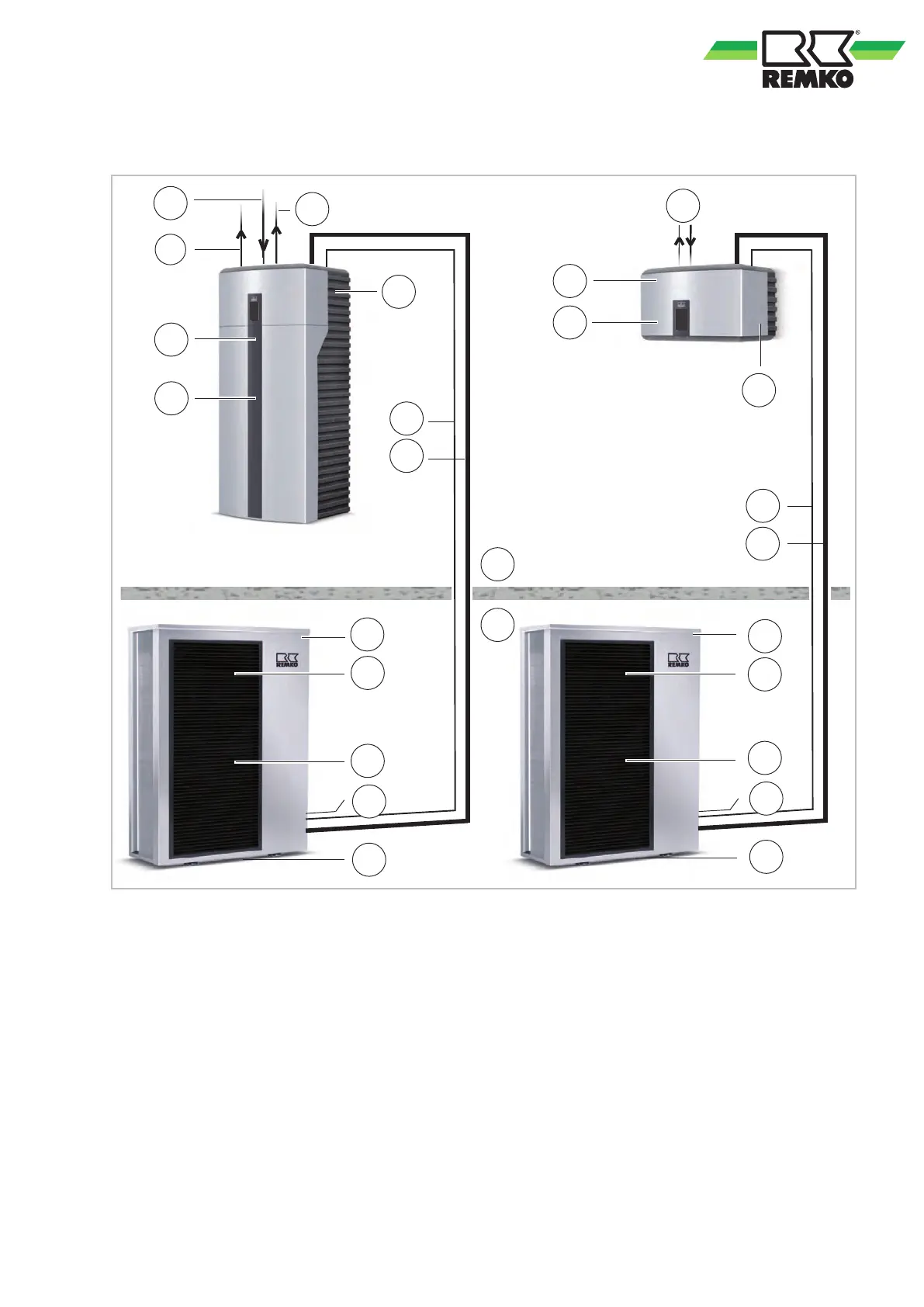
2.3 System layout WKF/WKF-compact 170
A
B
C1
1
3
5
6
7
C2
D1
D2
2
3
4
5
8
8
9
10
11
12
9
2
4
9
9
Fig. 3: System layout
A: Outdoor area
B: Indoor area
C1: Indoor unit WKF-compact 170
C2: Indoor unit WKF 170
D1: Outdoor unit WKF-compact 170
D2: Outdoor unit WKF 170
1: Common return flow (DN 25)
2: Condensate drain, outdoor unit (must contain
anti-freeze!)
3:
Refrigerant lines
3
/
8
” and
3
/
4
”
4: Outdoor unit power supply = 400V/3~/50Hz
3x20A (e.g. 5x2.5 mm
2
)
5: Indoor unit power supply = 230V/1~/50Hz
16A (e.g. 3x1.5 mm
2
)
6: Power supply for electrical auxiliary heater 9 kW
(e.g. 5x2.5 mm
2
)
7: Power supply for electrical auxiliary heater 9 kW
(optional) (e.g. 5x2.5 mm
2
)
8:
Control line shielded (e.g. 2x1 mm
2
)
9: Fan
10: Inlet for heating (DN 32)
11: Hot-water supply and return pipes (DN 32)
12: Inlet for hot-water tank (DN 32)
9
 Loading...