7.2 Electrical drawings
3
2
5
4
6
7
A
Fuse
1 3
4
1 5 62
1 3
4
1 2
1 3
4
1 52
ON
ON ON
SW2 SW1
SW3
ON/OFF
0-10V
GND
A
B
COM
AUX1
AUX2
H
M
L
AUTO
0-10V
ON/OFF
GND
A
B
CN9
JP1
AUX 2
COM
AUX 1
Auto
L
M
H
Value
L
N
GND1
FAN 2
FAN 1
RT OT
CN7
CN6
ALARM
ALARM
ALARM
8
1
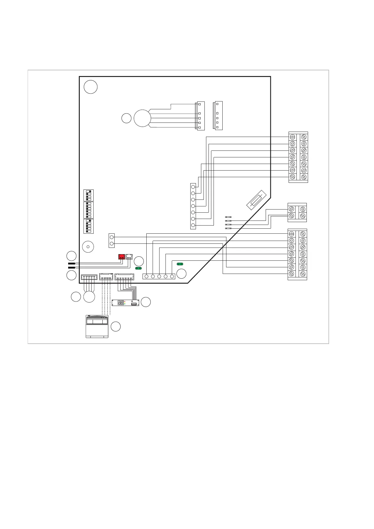
Fig. 34: Electrical drawings
A: Unit circuit board
1: Fan
2: Jumper JP1
When establishing group control, this jumper is
to be set on the last unit in the control chain on
the circuit board
3: Jumper CN9
open --> 0-5 V DC control
closed --> 0-10V DC control
4: Register probe
5: Room temperature probe
6: Swing motor
7: Display
8: Cabled remote control (optional)
REMKO WLT EC series
38
 Loading...