EasyManua.ls Logo

Remote Control RCEL - User Manual

Default Icon
8 pages
Print Icon
To Next Page IconTo Next Page
Loading...
Top Quality Valve Actuators
Made in Sweden
Instruction
Digital Controller PCU Solid State
RCEL
- 1 -
www.rotork.com www.remotecontrol.se
ELECTRICAL SHOCK HAZARD.To avoid serious personal injury,
property damage, turn off ALL power to the actuator before remov-
ing the cover.
Before installation or use, verify the nameplate information infor-
mation to insure the correct model number, torque, voltage and
enclosure type.
Be sure to completly review the actuator manual prior to operation.
Final limit switch adjustment MUST be done after mounting the ac-
tuator to the valve. Incorrect adjustment may cause actuator failure.
Over torque switches are factory set, tampering with the over
torque switch settings may damage the actuator and void the war-
ranty.
The actuator must be properly grounded. Use the grounding lugs
provided on the inside and outside of the actuator body.
To minimize the possible damage caused by condensation, be sure
to energize the heater.
Care should be taken when wiring 3 phase actuators.
Conrm proper rotation and limit switch shutoff function during the
initial operation. If the actuator rotates in the reverse direction, then
the phasing needs to be corrected by switching two of the 3 phase
wires on the terminal block.
CAUTION
Specications
Input Power
90~230V AC ±10%, 50/60Hz
DC 24V / AC 24V ±10%
Input Power must match motor Ratings
Command Signal
4~20mA DC (Default), 0~5VDC,
0~10VDC, 1~5VDC, 2~10VDC
Dead Band 1 ~ 7,5% (1 scale 0,5%)
Output Signal
4~20mA DC
Load Resistance
750
Ω
Terminals 1~12 Connector, +, - 2EA (In/Output)
Visual Indicators
4 LEDS,
Power (Blue), Fault (Yellow),
Open (Red), Close (Green)
Calibration Method ASCN (Autoscan) Button
Output Contact
Relay Contact 250V AC 16A MAX.
(Inductive Load)
Delay Time 1 Sec
Parameters
Dead Band: 0.2mA(Step)
Fail operation (during loss of command
signal) Select input signal. A FULL Set
or Clear
Resolution Min 1/1,000
Ambient Temperatur -10 ºC ~ +60 ºC
Ambient Humidity 90% RH MAX. (Non-Condensing)
Dielectric Strenght
1,500V AC 1 MIN.
(Input to Output to Power to Ground)
Insulation Resistance 500V DC 30MΩ MIN.
Warranty Information
The warranty will be void under the following conditions:
1. Failure or damage caused by misuse or abuse.
2. Failure or damage caused by unauthorized modications or repairs done to the actuator.
3. Failure caused by the unauthorized modication / change or the wiring.
4. Failure caused by water entering the actuator due to improper sealing of the conduit entries.
5. Failure caused by improperly set limit switches.
6. Failure caused by re, ood damage or other natural disasters.
7. Failure occuring more than one year after shipment date.
Question and Answer IconNeed help?

Do you have a question about the Remote Control RCEL and is the answer not in the manual?

Overview

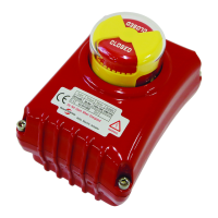
This document describes the RCEL Digital Controller PCU Solid State, a device designed for controlling valve actuators.

Function Description

The RCEL Digital Controller PCU Solid State is an electronic control unit for valve actuators, enabling precise control and monitoring of valve positions. It supports various input and output signals, allowing for integration into different control systems. The controller can operate in both automatic and manual modes, providing flexibility in operation. It features a dead band setting to prevent unnecessary actuator movement and includes various limit switches for safe operation, such as dry contact open and close limit switches. The device is designed to handle different power supplies and signal types, making it versatile for various industrial applications. It also incorporates troubleshooting features to help identify and resolve common issues.

Important Technical Specifications

Electrical Specifications:

  • Power Supply: 90-230V AC ±10%, 50/60Hz; DC 24V / AC 24V ±10%.
  • Input Signal: 4-20mA DC (default), 0-5VDC, 0-10VDC, 1-5VDC, 2-10VDC.
  • Output Signal: 4-20mA DC.
  • Load Resistance: 750Ω.
  • Terminals: 1-12 Connector, +, - 2EA (In/Output).
  • Visual Indicators: 4 LEDs (Power (Blue), Fault (Yellow), Open (Red), Close (Green)).
  • Calibration Method: ASCN (Autoscan) Button.
  • Output Contact: Relay Contact 250V AC 16A MAX (Inductive Load).
  • Delay Time: 1 Sec.

Performance Specifications:

  • Dead Band: 0.2mA (Step). This feature prevents unnecessary actuator movement when the input signal is within the dead band.
  • Resolution: Min 1/1,000.
  • Ambient Temperature: -10 °C ~ +80 °C.
  • Ambient Humidity: 95% RH MAX (Non-Condensing).
  • Dielectric Strength: 1,500V AC 1 MIN (Input to Output to Power to Ground).
  • Insulation Resistance: 500V DC 30MΩ MIN.

The controller's PCU board features several key components:

  • No. 1-12 Connector: For connecting various inputs and outputs.
  • Dip Switch: Configures input signal types and other settings.
  • Input Connector: For connecting the control signal.
  • Output Connector: For connecting the actuator's feedback signal.
  • ZERO Button: Used for calibration and setting the zero point.
  • SPAN Button: Used for calibration and setting the span.
  • AUTO SCAN Button: Initiates automatic calibration.
  • Dead Band Potentiometer: Adjusts the dead band setting.
  • OTS, CTS Connector: For connecting open and close torque switches.
  • OLS, CLS Connector: For connecting open and close limit switches.
  • Potentiometer Connector: For connecting the position feedback potentiometer.
  • DIP switch for Input Setting: Configures the input signal range (e.g., 4-20mA, 0-10V).

Usage Features

Installation and Wiring:

  • Electrical Hazard: Proper wiring is crucial. All power to the actuator must be removed before removing the cover.
  • Nameplate Information: Before installation or use, verify the nameplate information to ensure the correct model number, torque, voltage, and enclosure type.
  • Wiring Diagram: A detailed wiring diagram is provided, showing connections for AC power, input, output, and various control signals (Close, Open, Auto, Com, ACLS, Com, AOLS).
  • Grounding: Ensure proper grounding to prevent voltage feedback and actuator damage.
  • Cable Glands: Use appropriate cable glands for wiring to maintain the enclosure's integrity.

Operation Modes:

  • Automatic Mode: The actuator operates based on the input signal. The controller automatically adjusts the valve position to match the input signal.
  • Manual Mode: Allows for manual operation of the actuator using a lever. This is useful for initial setup, maintenance, or in case of power failure. To engage manual mode, the lever on the side of the actuator handle must be moved.
  • DIP Switch Settings: The DIP switches allow configuration of various parameters, including:
    • Fail Close/Open: Defines the actuator's behavior in case of signal loss (moves to full close or full open).
    • AF (Auto Full): If the input signal is outside the specified range, the actuator moves to a full open position.
    • CH1/CH2: Used for controlling the input signal and manual handle operation.
    • REV (Reverse Action): Reverses the actuator's direction of operation.
    • Full Close/Open Output Control: Defines the output current when the actuator reaches full close or full open.

Calibration:

  • Auto Scan Button: Pressing this button for at least 2 seconds initiates an automatic calibration process, which sets the zero and span points.
  • ZERO Button: Used to set the zero point of the actuator.
  • SPAN Button: Used to set the span of the actuator.
  • Potentiometer Setting: The potentiometer can be adjusted to fine-tune the actuator's position feedback. This is critical for accurate control.

Limit Switches:

  • Close/Open Limit Switches: These switches define the physical limits of the actuator's travel. They must be properly set to prevent over-travel.
  • Torque Switches (OTS/CTS): These switches protect the actuator from damage due to excessive torque.

Maintenance Features

Troubleshooting: The manual provides a comprehensive troubleshooting guide for common issues:

  • Manual override will not move: Check for jammed worm wheel and mechanical limit stop. Solution: Loosen the mechanical limit stop and valve mounting bolts, correct the mechanical stop position, and secure the mounting bolts and limit stop.
  • Actuator to move the handle when not in operation: Check for limit switch malfunction or incorrect mechanical limit stop setting. Solution: Reset the limit switch cam and reset the mechanical limit stop.
  • Actuator suddenly stops during operation: Check for over torque switch trip. Solution: Valves torque has increased. Reset the valve and check for damage.
  • When the motor does not operate: Check for main power failure, wire disconnect or shot circuit, or motor/condenser damage. Solution: Check main power, replace defective wire, or replace motor/condenser.
  • When 3 phase operation rotates actuator in the opposite direction than the signal is applied: Check for phase reversal. Solution: Switch two of the three phase wires.
  • When actuator continues to rotate even after the cam strikes the limit switch: Check for input failure circuit & disconnection. Solution: Input check.
  • PCU board FAULT LAMP flashes: Check for potentiometer disconnection. Solution: Potentiometer check.
  • PCU board FAULT LAMP lighted, When the lights OPEN LAMP: Check for potentiometer P1, P3 reversal. Solution: P1, P3 re-wiring.

General Maintenance:

  • Regular Inspection: Periodically inspect the device for any signs of wear, damage, or loose connections.
  • Cleaning: Keep the device clean and free from dust and debris.
  • Firmware Updates: While not explicitly mentioned, keeping the device's firmware updated (if applicable) can improve performance and address bugs.
  • Potentiometer Calibration: Regularly check and recalibrate the potentiometer to ensure accurate position feedback.
  • Limit Switch Adjustment: Periodically verify the settings of the close and open limit switches.
  • Wiring Integrity: Ensure all wiring is secure and free from damage. Remove any loose debris or wires.
  • Cover Security: After any maintenance or inspection, ensure the top cover is securely fixed with all six cover screws.

Important Warnings:

  • Electrical Hazard: Always disconnect power before performing any maintenance or inspection.
  • Potentiometer Warning: When setting the resistance value on the potentiometer, always operate when the actuator power is OFF. If the power is ON, the resistance value on the calibrator will not show accurately.
  • Warranty: The warranty will be void under certain conditions, such as damage caused by misuse or abuse, unauthorized modifications, or repairs.

Remote Control RCEL Specifications

General IconGeneral
BrandRemote Control
ModelRCEL
CategoryController
LanguageEnglish

Related product manuals