RL78/G13 Handshake-based SPI Master Transmission/Reception
R01AN6883EJ0100 Rev.1.00 Page 23 of 38
June.15.23
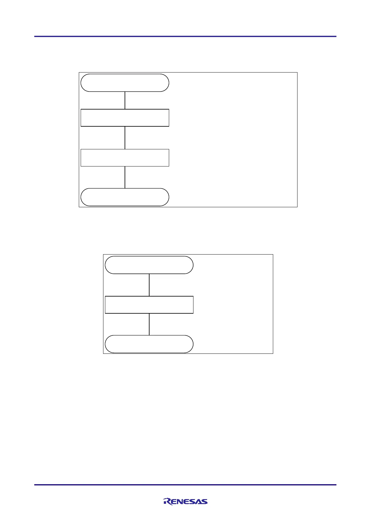
5.6.3 CPU clock Configuration
Figure 5-3 shows the flow of CPU clock Configuration.
Figure 5-3 CPU clock Configuration
R_CGC_Create()
High-speed system clock / Subsystem
Clock Settings
CMC resistor ← 00H : High-speed system clock,
MSTO P b it ← 1 Subsystem clock not used
XTSTOP bit ← 1
return
CPU/peripheral hardware clock (fCLK)
selection
MCM bit
← 0 : High-speed OCO clock (fIH) selected
for main system clock (fMAIN)
CS S b it ← 0 : Select main system clock (fMAIN) for
CPU/peripheral hardware clock (fCLK)
5.6.4 Port Configuration
Figure 5-4 shows the flow of Port Configuration.
Figure 5-4 Port Configuration
R_PORT_Create()
Set P5 to input mode
P5 resistor ← 0CH
PM5 resistor ← F3H
return

 Loading...


