RL78/G13 Handshake-based SPI Master Transmission/Reception
R01AN6883EJ0100 Rev.1.00 Page 4 of 38
June.15.23
1. Specifications
The serial array unit (SAU) described in this application note performs CSI master transmission/reception.
The chip select
(CS) signal uses the port.CS Handshake processing using the BUSY signal is also performed
for the slave device selected by the CS
signal.
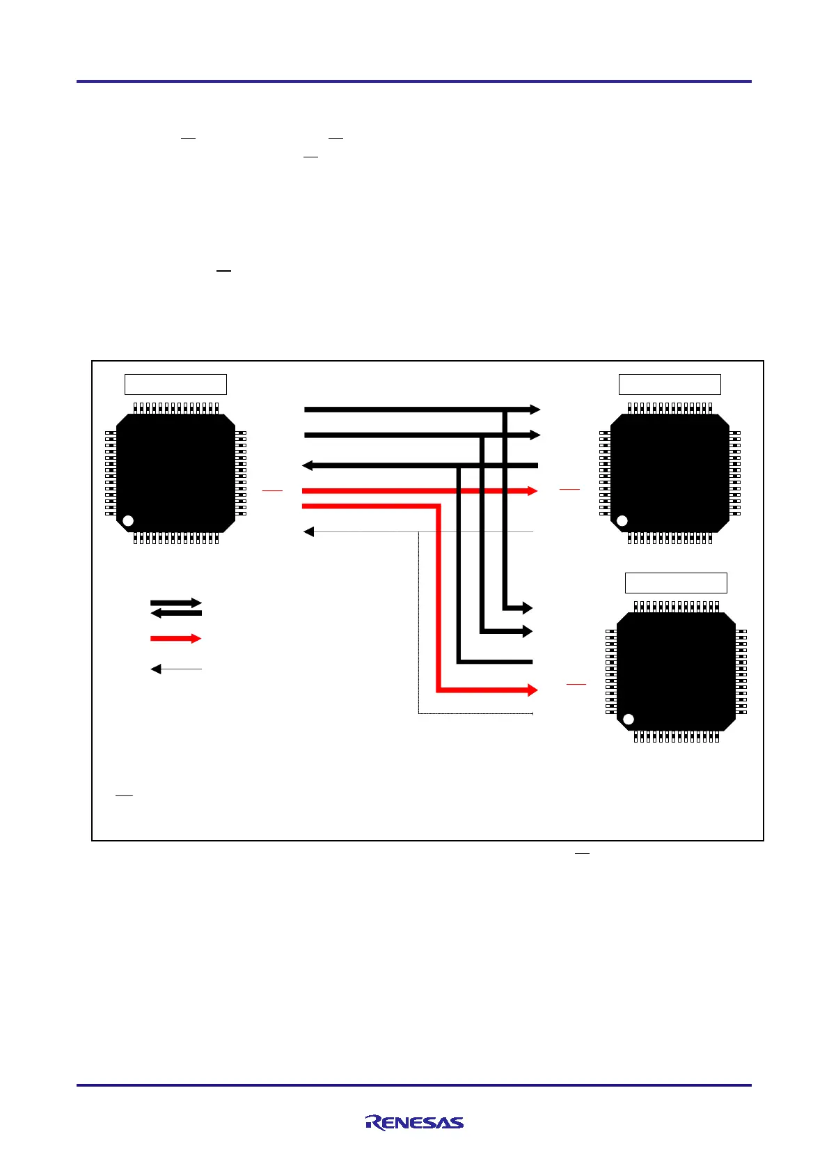
1.1 Outline of CSI Communication
CSI communication is clock-synchronous serial communication using three signal lines, namely, serial
clock (SCK), serial data input (SI), and serial data output (SO). SPI (Serial Peripheral Interface) uses an
additional chip select
(CS) signal to select the slave device. The relationship among these signals is shown in
Figure 1-1.
Figure 1-1 Outline of CSI Communication
RL78/G13
RL78/G13
Master Slave 1
SCK
SO
SI
BUSY
RL78/G13
Slave 2
CS
Serial clock (output)
Serial data (output)
Serial data (input)
SCK
SI
SO
BUSY
CS
SCK
SI
SO
BUSY
CS
Simple SPI (CSI) signals
Additional signal for SPI
BUSY signals
SCK signal
: Serial clock signal. Output by the master.
SO signal
: Serial data output signal Connected to the SI signal pin of the target device.
SI signal : Serial data input signal. Connected to the SO signal pin of the target device.
CS signal : Used by the master device to select the target slave device.
BUSY signal
: Handshake signal used in this application note.
Slave select signal (output)
The master first selects the slave with which it wants to communicate with the CS signal. Then, the master
outputs data to the SCK signal line and the SO signal line in synchronization with the SCK signal, and inputs
data from the SI signal line.
In SPI/CSI communication, the slave needs to become ready for communication by the time the master
starts communication (sending the SCK signals). In this application note, the BUSY signal is used to confirm
that the slave is ready for communication. The master detects a low-level BUSY signal and then initiates a
communication session.
 Loading...


