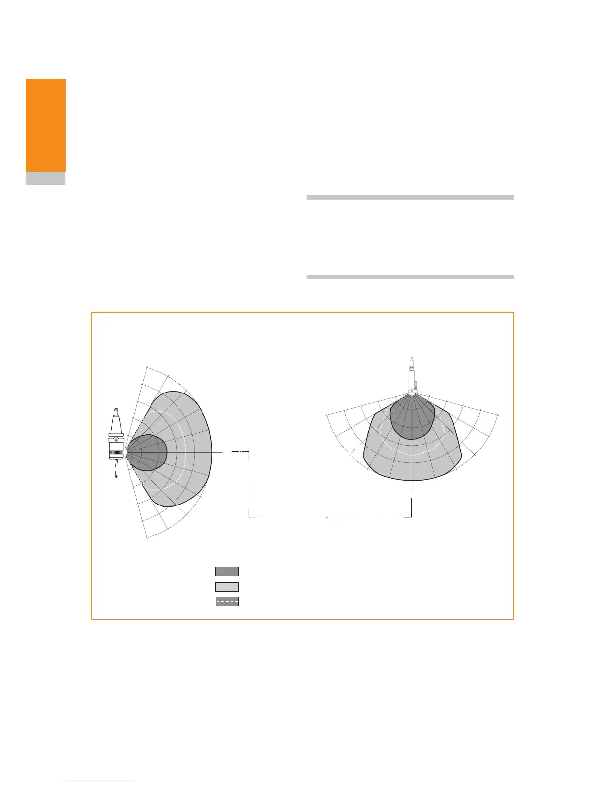
Typical plot at 20 °C (68 °F)
360° transmission around
probe axis in metres (feet)
Range m (ft)
Switch on / switch off
Operating – standard power mode
Operating – low power mode
Typical plot at 20 °C (68 °F)
360° transmission around
probe axis in metres (feet)
OMP400,
OMP40-2
or OLP40
75°
60°
45°
30°
15°
0°
15°
30°
45°
60°
75°
75°
60°
45°
30°
15°
0°
15°
30°
45°
60°
OMM-2C
75°
Optical centre line
2.5 (8.2)
2.0 (6.5)
1.5 (4.9)
1.0 (3.3)
0.5 (1.6)
Performance envelope of
OMM-2C with OMP400, OMP40-2
or OLP40
Reflective surfaces within the machine cabinet
may increase the signal transmission range.
Coolant residue accumulating on the windows of
the OMM-2C and OMP will have a detrimental
effect on transmission performance. Wipe the
windows clean as often as necessary to maintain
unrestricted transmission.
For best system performance, ensure the
OMM-2C is mounted in a position which is not
directly in front of a light source.
The probe and OMM-2C may deviate from the
optical centre line, provided opposing light cones
always overlap, with transmitters and receivers in
the other’s field of view (eye-to-eye).
In multiple probe mode applications, OMP400
may be configured as Probe 1 or Probe 2 and
OMP40 or OLP40 may be configured as Probe 1,
Probe 2 or Probe 3.
CAUTION: If two systems are operating in close
proximity, take care to ensure that the signals
transmitted from the OMP on one machine are not
received by the OMM-2C on another machine and
vice versa.
2.5 (8.2)
2.0 (6.5)
1.5 (4.9)
1.0 (3.3)
0.5 (1.6)



 To Next Page