Primo system installation guide
ii
Contents
Recalibration ...............................................................2.2
Acquisition mode
............................................................2.2
Primo Credit Token
..........................................................2.3
Primo Upgrade Credit Token
................................................2.3
Credit transfer
............................................................ 2.3
How to purchase a credit token
..............................................2.3
Low credit indicators. . . . . . . . . . . . . . . . . . . . . . . . . . . . . . . . . . . . . . . . . . . . . . . . . . . . . . . 2.3
Part setter operation
.........................................................2.4
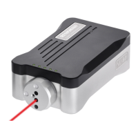
Tool setter operation
.........................................................2.4
Software routines
...........................................................2.5
Primo™ Interface basics .....................................................3.1
Introduction
................................................................3.1
Power supply
............................................................3.1
Interface visual diagnostics
.................................................3.1
Interface inputs
.............................................................3.2
Interface outputs
............................................................3.2
SSR outputs specifications
.................................................3.2
Interface output waveform
.....................................................3.3
Switches SW1 and SW2
......................................................3.4
Switch SW1 output configuration
.............................................3.5
Switch SW2 output configuration
.............................................3.5
Dimensions and specifications ...............................................4.1
Part setter dimensions
........................................................4.1
Tool setter dimensions
........................................................4.2
Interface dimensions
.........................................................4.3
Part setter specification
.......................................................4.4
Tool setter specification
.......................................................4.6
Interface specification
........................................................4.8
System installation ...........................................................5.1
Operating envelope
..........................................................5.1
Signal LED
................................................................5.1
Performance envelope. . . . . . . . . . . . . . . . . . . . . . . . . . . . . . . . . . . . . . . . . . . . . . . . . . . . . . . . 5.2
Equipment positioning
.....................................................5.2
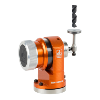
Preparing the part setter
......................................................5.3
Fitting the stylus
..........................................................5.3
Installing the battery
.......................................................5.4
Mounting the part setter on a shank. . . . . . . . . . . . . . . . . . . . . . . . . . . . . . . . . . . . . . . . . . . 5.5
Part setter stylus on-centre adjustment
........................................ 5.6
 Loading...