Do you have a question about the Renishaw PH10 Series and is the answer not in the manual?
Overview of the user's guide and its purpose.
Form to register as a PH10 system user for product updates.
Describes the purpose and content of the user's guide for PH10 series.
Overview of the PH10 series probe heads (PH10T, PH10M, PH10MQ).
Key features of the PH10 series heads, including indexing positions and repeatability.
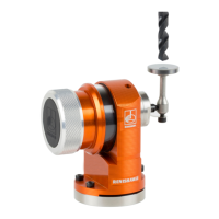
Details and illustration of the PH10T motorised probe head.
Details and illustration of the PH10M motorised probe head.
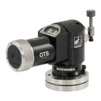
Details and illustration of the PH10MQ motorised probe head.
Technical specifications for PH10T, PH10M, and PH10MQ probe heads.
Information about the PHC10-2 controller for the PH10 system.
Technical specifications for the PHC10-2 controller.
Description of the LEDs and controls on the PHC10-2 front panel.
Identification of connectors and switches on the PHC10-2 rear panel.
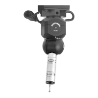
Details about the optional HCU1 hand control unit for manual operation.
Overview of extensions, probes, and styli compatible with PH10T.
Methods for connecting probes and extensions, including M8 and Autojoint.
Connecting probes/extensions with M8 thread to PH10T.
Connecting probes/extensions using the autojoint system.
Information on touch-trigger probes for PH10 heads.
Details on M8 touch-trigger probes and their user guides.
Information on multiwire probes compatible with PH10M/PH10MQ.
Types of extension bars for PH10 heads.
Range of precision styli and stylus accessories.
Description of AM1 and AM2 adjustment modules for PH10 heads.
Using the gram gauge to measure probe trigger force.
Using the machine checking gauge for CMM performance.
Features of the universal datum sphere for probe qualification.
Overview of ACR1 and ACR3 autochange racks for probe exchange.
Basic installation configuration for the PH10 system.
Explanation of manual and automatic operating modes for the PH10 system.
Guide to identifying and solving system problems.
Common causes and solutions for poor measurement performance.
Troubleshooting steps for when there is no probe signal.
Possible causes and remedies for the head not moving.
Causes and solutions for the DATUM ERROR LED indication.
Troubleshooting steps for an Obstruct error.
Causes and remedies for the OVERLOAD ERROR LED indication.
Information on user-serviceable parts and returning defective units.
Instructions for safely cleaning the probe head, controller, and hand control unit.
| A-axis rotation | ±180° |
|---|---|
| Power Supply | 24 V DC |
| Communication Interface | RS232 |
| Repeatability | 0.4 µm (PH10MQ PLUS) |
| Storage Temperature | -20°C to 70°C |