Do you have a question about the Renishaw PH10 and is the answer not in the manual?
Information regarding FCC compliance for digital devices and potential interference.
Details TÜV certification for compliance with OSHA and SCC standards.
Lists related user guides and technical specifications for the PH10 system.
Details the PH10T, PH10M, PH10MQ heads and their common features.
Describes the PHC10-2 controller's function, power supply, and interface capabilities.
Illustrates system configurations for PH10T/PH10M with two-wire and multiwired probes.
Shows the range of probes, extensions, and styli compatible with PH10 heads.
Provides dimensions for PH10T and PH10M heads and installation notes.
Covers installation of the PHC10-2 controller as a stand-alone unit or in a 19" rack.
Details the pin configuration for the PHC10-2 RS232 rear panel connector.
Explains how to set the baud rate for RS232 communication using rear panel switches.
Describes basic and extended command set modes for RS232 protocol.
Lists pin numbers and signals for the PHC10-2 IEEE488 connector.
Shows the capability codes supported by the PHC10-2 IEEE interface.
Explains how to select IEEE device address and parallel poll bits via switches.
Describes switch settings for PICS interface configuration on the PHC10-2.
Details switch settings for 5-pin or 7-pin DIN interface connections.
Explains how to enable/disable HCU1 probe damp and reset buttons via a switch.
Details switch settings for selecting PICS or DIN output configurations.
Explains the probe reset timer function and switch settings for reseat duration.
Lists signal names, cable colours, and specifications for head connection cables.
Provides a summary of switch settings for RS232 and IEEE configurations.
Describes the HCU1 as a remote unit for manual mode and teach cycles.
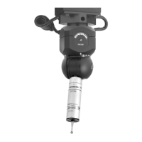
Details the AM1 module for fine adjustment in pitch, roll, and yaw.
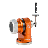
Describes the AM2 module for fine adjustment in pitch, roll, and yaw for PH10MQ.
| Brand | Renishaw |
|---|---|
| Model | PH10 |
| Category | Laboratory Equipment |
| Language | English |