25
Probing system output (RS232 and IEEE)
6.4.2 SSR output
The pin numbers and descriptions are given in table 12.
Table 12 - SSR connector pinouts
Pin Description Pin Description
1
2
3
4
Head LED cathode
Ground
HEAD LED cathode
Probe return
5
6
7
Probe signal
Probe inhibit
Probe inhibit
6.5 Probe reset time
The probe reset timer on the PHC10-2 unit (later than version 5) is designed to be used where the touch
probe fails to remain seated following a head index move.
The timer enables the duration permitted for a probe reseat to be extended. It is designed to be used in
the event that a probe fails to rearm following a head index when using long extension bars.
Table 13 - Probe reset time
Switch Description Position
10
Time permitted for probe to
reseat following a head index
UP Level 2 (extended)
DOWN Level 1 (standard)
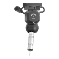
6.6 Head connector and cables
Head cable numbers, descriptions and currents are set out in table 14.
NOTE: For maximum immunity from electrical noise, Renishaw recommends that:
1. Mating connectors must be metal bodied.
2. The overall cable screen is continuous and connected to the system ground on the user’s
equipment through the bodies of the connectors.
CAUTION: For correct system function, the maximum overall single core resistance between the
head and PHC10-2 should be 2.5W.
Table 15 shows the range of standard motorised head cables available from Renishaw.