24
Probing system output (RS232 and IEEE)
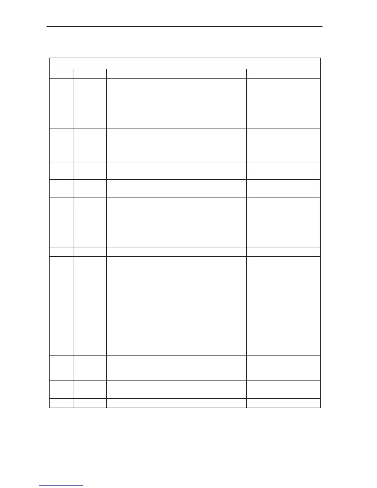
Table 11 - PICS connector pinouts
Pin Signal Position
1 STOP
This signal is active when low and is responded
to, and can be asserted by the PHC10-2. See
Section 8 for an explanation of the conditions which
will cause the PHC10-2 to assert STOP, and the
reaction of the PH10 system to an external STOP
signal.
Read from PHC10-2 to
indicate an error in the
PH10 system. Pull down
to 0 V to indicate a STOP
condition external to the
PH10 system.
2
PPOFF
(probe
power
OFF)
PPOFF is an active low inhibit signal which can be
set by the CMM computer or the PHC10-2. PPOFF
is overridden by the use of the STOP signal.
Pull down to 0 V to turn off
power to the probe.
3 0 V
This the common reference and return path for all
signals.
-
4
LED
anode
This is a constant current input, normally from the
interface to illuminate the head LED.
-
5
Probe
signal
This pin and pin 9 transmit the probe output signals
from the PHC10-2 when a multiwire cable is not in
use. As these signals have not been interfaced, it is
important that the PICS cable between the PHC10-2
and the interface is less than 0.5 m (1.6 ft) otherwise
interference from other PICS signals can occur.
-
6 SPARE - -
7
PDAMP
(probe
DAMPing)
PDAMP is an active low signal which can be set
by the CMM computer, the PHC10-2 or by the
optional HCU1. PDAMP can influence an interface
by reducing electronically the sensitivity of a strain
gauge based probe. It can inhibit a Renishaw
interface, when standard touch trigger probes are in
use, until the probe has been continuously triggered
for at least 5 ms. The signal can be asserted by
the CMM computer to reduce the sensitivity of the
probe. This will reduce unwanted triggers during
CMM acceleration, or vibration during position
moves, whilst maintaining crash protection.
Pull down to 0 V to
partially inhibit the probe
during rapid moves.
8 LEDOFF
This signal is not asserted by the PHC10-2, but it
responds to LED OFF by switching the head LED
off.
-
9
Probe
return
See pin 5 -
Screen - -