22
Probing system output (RS232 and IEEE)
6 Probing system output (RS232 and IEEE)
Both versions of the PHC10-2 have a further eight configuration switches (switches 11 to 18) on the rear
panel. These allow selection of output configurations for interconnections.
Not all of the switches are used. They are included on the controller to allow a standard switch
configuration for the range of Renishaw’s motorised head controllers.
NOTE: If a switch has no specified function, it should be set in the DOWN position.
6.1 PICS interface configuration
If the PHC10-2 is to be used in a PICS linked system, the configuration option is selected using switch 11
(see table 7).
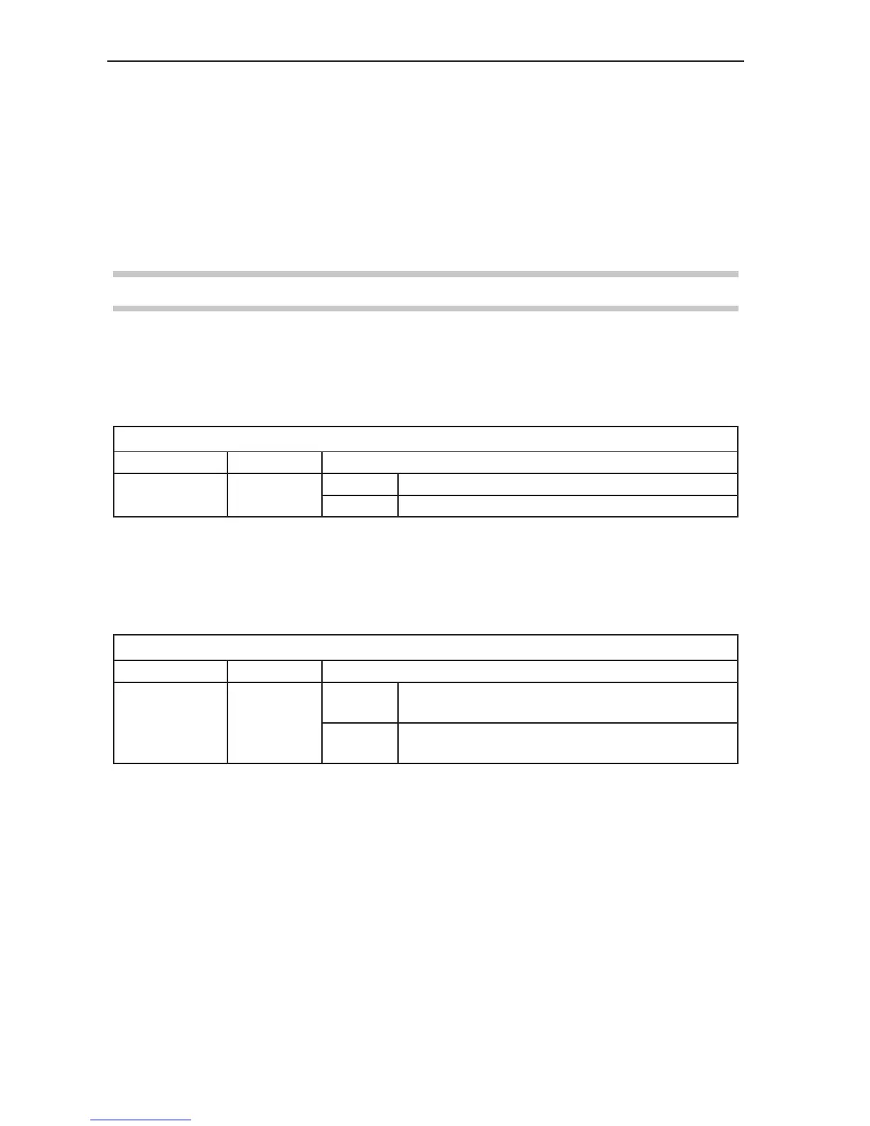
Table 7 - PICS interface configuration
Switch Description Position
11
PICS
configuration
UP PPOFF and PDAMP active during head index
DOWN PDAMP only active during head index
6.2 Interface connection
If the PHC10-2 is to be used in a 5 pin or 7 pin linked system, the configuration option is selected using
switches 17 and 18 (both UP or both DOWN) (see table 8).
Table 8 - Interface connection
Switch Description Position
17 and 18
Interface
connection
UP
PICS or 7-pin DIN operation: the PHC10-2 internal
inhibit relay disables the interface during a head index
DOWN
5-pin DIN operation only: the PHC10-2 internal inhibit
relay disables the probe during a head index