System description
2.8.3 PHC10-2 rear panel
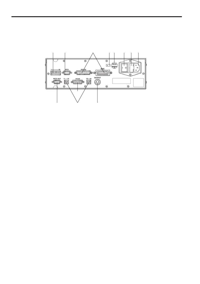
Figure 6 shows the rear panel of the PHC10-2.
Figure 6 - Rear panel
1 2 3 4 5 6 7 8
9 10
11
12
Key
1 Switches 1-10, communications protocol selection
2 HCU1 connector
3 Either RS232 communications connector or IEEE488 communications connector
4 Version number
5 Serial number
6 Main power ON/OFF switch
7 Fuse holder
8 Mains power input
9 PICS output connector
10 Switches 11-14 and 15-18, probing system format selection
11 Probe head connector
12 Probe output connector
The UCC daughtercard (PHC1050) has its own installation guide (H-1000-5226)
which exists on the UCC CD (A-1333-0080).

 Loading...