Do you have a question about the Renishaw TS27R and is the answer not in the manual?
Guidance for users, suppliers, and installers on safety precautions, hazard awareness, and regulatory compliance for the TS27R.
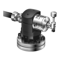
Overview of interface units (MI 8-4, HSI, HSI-C) and a diagram of TS27R probe components.
Explains the TS27R probe's function for tool setting, broken tool detection, and axis alignment on CNC machines.
Step-by-step instructions for mounting the TS27R probe and fitting Spirol pins for remounting.
Descriptions of MI 8-4, HSI, and HSI-C interfaces, including their functions and connections.
Detailed wiring diagram for the HSI-C interface, including standard probe connection note.
Wiring diagram for the HSI interface, including standard probe connection note.
Detailed wiring schematic for the MI 8-4 interface, showing inputs, outputs, and power connections.
Instructions for fitting the stylus and captive link, including component diagrams and screw torque values.
Explains how to achieve level stylus surface front-to-back and side-to-side using adjustment screws.
Guidance on service routines, general probe maintenance, and diaphragm seal inspection.
Detailed steps for diaphragm maintenance, including component removal, cleaning, inspection, and refitting.
| Type | Tool setting probe |
|---|---|
| Hard-wired | Yes |
| Repeatability | 1.0 µm (0.00004 in) 2σ |
| Stylus Tip Diameter | 2 mm |
| Operating Voltage | 5 V DC |
| Operating Temperature Range | 5°C to 50°C |
| Storage Temperature Range | –10°C to 70°C |