17
NOTE: The values found in your controller are default values and will not
necessarily match the ones listed. The values on this table are to show the user
what the different screens are used for.
NOTE: You do NOT have to program the control. These parameters are for extra
features. Once you connect the battery the settings are automatically synced.
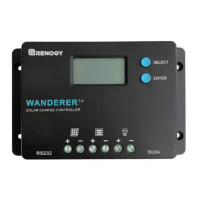
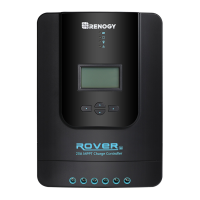
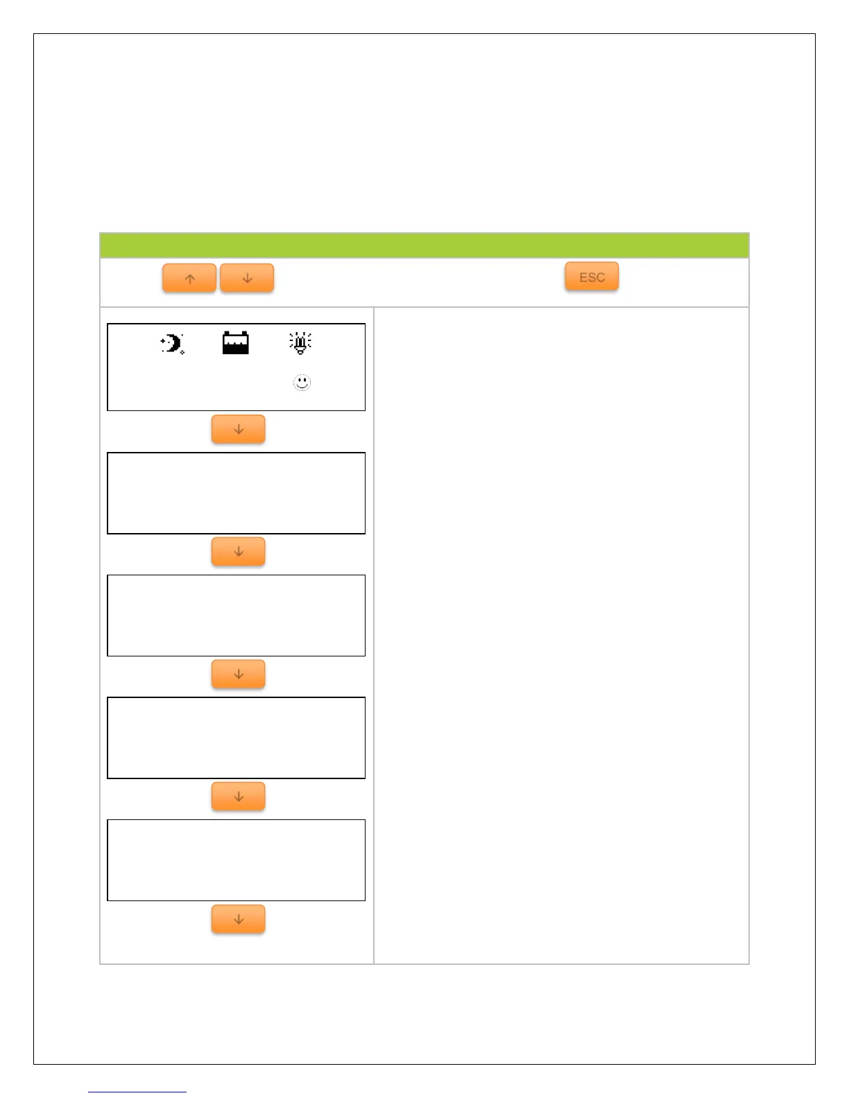
Default monitoring screen displaying charge controller
system status through icons.
Indicates battery voltage and battery current
Indicates the maximum and minimum battery values
since the charge controller has been turned on. When
battery is charging, the values are expected to
change.
Displays the battery state as well as the state of
charge of the battery.
NOTE: The Battery SOC% is an estimation based on
the charging voltage.
Displays the charging state of the battery as well as
the voltage coming from the PV module(s).
NOTE: Make sure PV input is not more than 150 VDC