Operating Instructions
Interface Programming
REOVIB MFS 268 - RS 232
5
3.1 Normal operation
In normal operation the serial interface is used to adjust the set point for the feeder throughput and the
digital control signals e.g. the enable. The unit status (ready or fault) is reported.
All data words are in the range 0000..FFFF H.
The communications words are shown in bit form as follows.
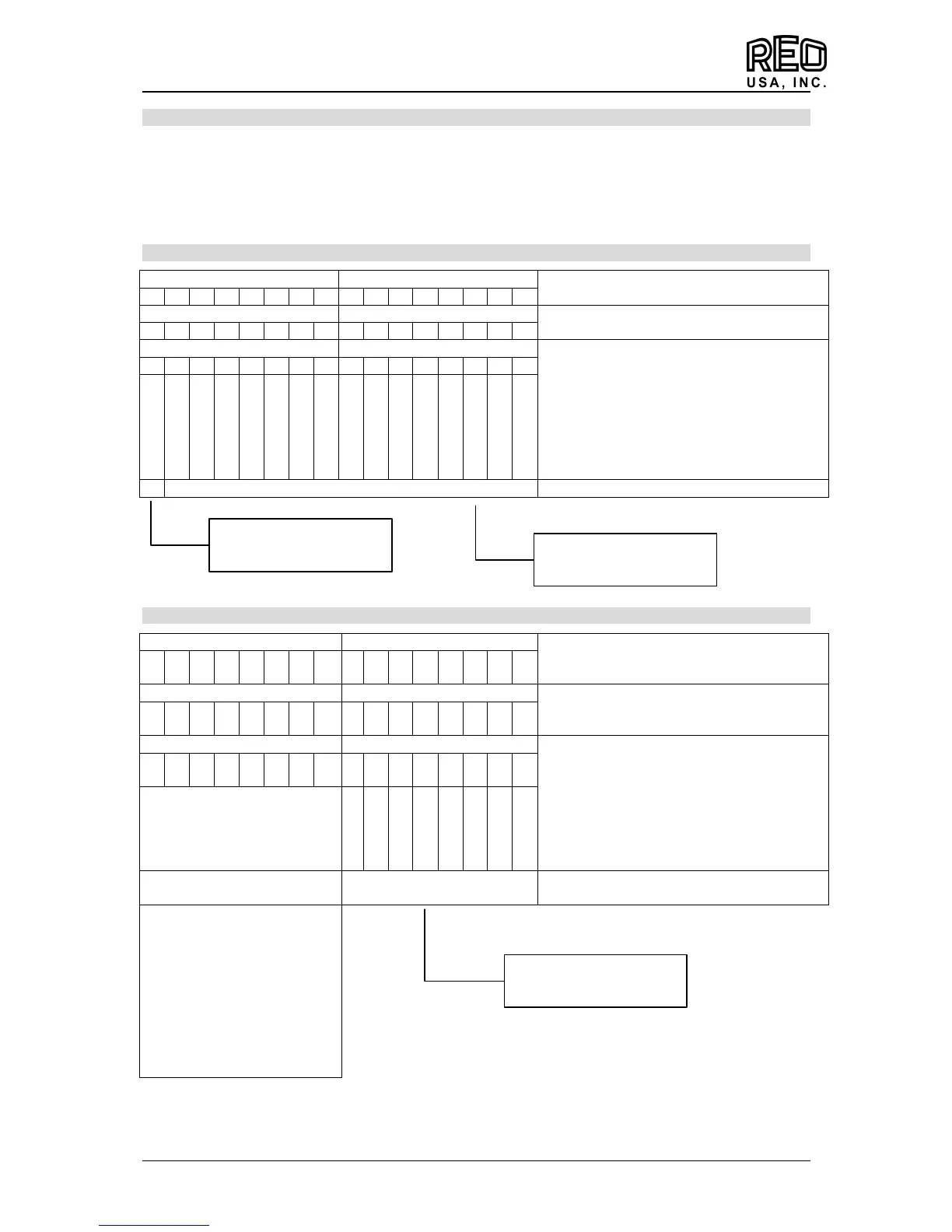
3.1.1 Transmission to the controller
H-Byte L-Byte
Set point 1, 16-Bit 100 % = FFFF H
15
11 10 9 8 7 6 5 4 3 2 1 0
H-Byte L-Byte
11 10 9 8 7 6 5 4 3 2 1 0
H-Byte L-Byte
Control word
Bit = „1“ = Function ON
All non used bits must be “0“
15
11 10 9 8 7 6 5 4 3 2 1 0
0 Mode bit
0
0
0
0
0
0
0
0
0
0
0
0
0 Enable
0
0
Control information (unit specific)
3.1.2 Response from controller
H-Byte L-Byte
Vibration acceleration feedback
16 Bit 100% = 8000H
15
11 10 9 8 7 6 5 4 3 2 1 0
H-Byte L-Byte
Feedback output current
16 Bit 100% = 8000H (% of rated current)
15
11 10 9 8 7 6 5 4 3 2 1 0
H-Byte L-Byte
Status word
X = not defined
Bit = “1“ = Function ON
15
11 10 9 8 7 6 5 4 3 2 1 0
Fault code
Status information
Unit specific
00
A5 (H)
57 (H)
58 (H)
02 (H)
0C (H)
05 (H)
70 (H)
C0 (H)
Unit not responding
Ready
ERROR Peak
ERROR OC
ERROR OL
ERROR ACC
ERROR OU
Over temperature
Feedback
Parameter mode
The unit status and the output current is reported.
0 = Normal operation
1 = Parameter operation
Enable bit
OFF bit
Report
 Loading...