Do you have a question about the REPLIGEN XCell ATF Series and is the answer not in the manual?
Explains the alternating tangential flow generated by the diaphragm pump.
Outlines the functionalities and goals of the C410v4B controller.
Describes the three main components of the controller system.
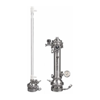
Details the stainless steel filtration assembly components.
Lists the components and connections within the Pneumatics Box.
Details the HMI and PLC components within the Electrical Box.
Lists the components found in the Power Box.
Explains the air inlet and exhaust/vacuum line connections.
Details power connection, switch, and stop button.
Describes sensor inputs, Ethernet/Profibus, and relays.
Explains how the controller manages diaphragm pump operation and flow.
Details the algorithms used for diaphragm pump cycle control.
Describes the HMI interface, primary screens, and their functions.
Provides a step-by-step guide for initial system setup and operation.
Offers guidelines for optimizing operating conditions with practical examples.
Details the procedure for disconnecting the assembly from the bioreactor.
Describes the steps for removing the Hollow Fiber Module.
Explains the process for inserting a new Hollow Fiber Module.
Provides instructions for replacing a screen module.
Outlines the procedure for replacing the diaphragm in the pump.
Details pre-autoclaving checks and assembly preparation.
Describes recommended autoclave cycle parameters and procedures.
Explains the sterilization process for the filtrate/harvest line.
Provides the procedure for making a hard, steam-sterilizable connection.
Recommends diaphragm replacement and proper seating.
Advises on the replacement schedule for the air inlet filter.
Specifies replacement intervals for O-rings and gaskets.
| Filtration Method | Tangential Flow Filtration (TFF) |
|---|---|
| Type | XCell ATF System |
| Application | Cell Culture Harvest, Clarification, Concentration, Diafiltration |
| Technology | Alternating Tangential Flow (ATF) |
| Applications | Cell Therapy, Vaccine Production |
| Volume Range | 1 L to 2000 L |
| Membrane Area | 0.1 m² to 10 m² |
| Compatibility | Compatible with various cell types and media |
| Dimensions | Varies by model |
| Weight | Varies by model |
| Power Requirements | 100-240 VAC, 50/60 Hz |