2.2 Electrical connection
WARNING! Electric shock!
Upon opening the housing, live parts are exposed!
Î Always disconnect the device from power supply
before opening the housing!
ATTENTION! ESD damage!
Electrostatic discharge can lead to damage to electronic com-
ponents!
Î Take care to discharge properly before touching
the inside of the device!
Note:
The pump speed must be set to 100 % when auxiliary relays or valves are
connected.
Note:
Connecting the device to the power supply must always be the last step
of the installation!
Note:
It must be possible to disconnect the device from the mains at any time.
Î Install the mains plug such that it is accessible at any time.
Î If this is not possible, install a switch that can be accessed.
Do not use the device if it is visibly damaged!
The power supply of the controller must be carried out via an external power
switch. The power supply of the device must be 100 … 240 V~ (50 … 60 Hz). Attach
flexible cables to the housing with the enclosed strain relief and the corresponding
screws.
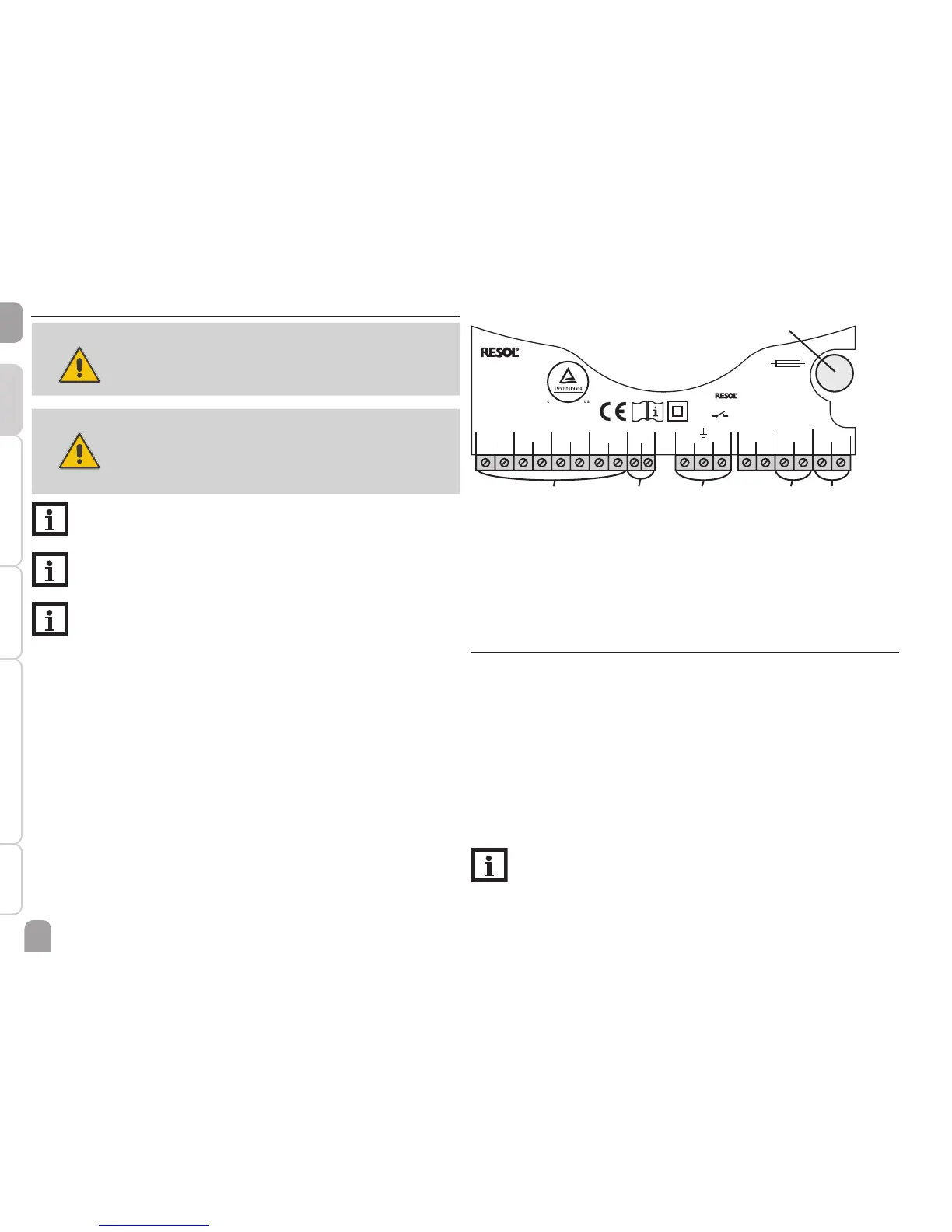
The controller is equipped with 1 semiconductor relay to which a load such as a
pump, a valve, etc. can be connected:
• Relay 1
18 = Conductor R1
17 = Neutral conductor N
13 = Grounding terminal
The mains connection is at the following terminals:
19 = Neutral conductor N
20 = Conductor L
12 = Grounding terminal ⌯
VBus
®
Made in Germany
DE-45527 Hattingen
DeltaSol BS/2 V2
IP 20
T4A
100 ... 240 V~
50-60 Hz
CU 72091163 01
Temp. Sensor Pt1000
S1 S2 S3 S4 R1VBus
1234 567891012131417181920
NNL
1 (1) A 100 ... 240 V~
mains terminals
fuse
load terminalssensor terminals
grounding
terminals
Connect the temperature sensors (S1 to S4) to the corresponding terminals
with either polarity:
1 / 2 = Sensor 1 (e. g. collector sensor)
3 / 4 = Sensor 2 (e. g. store sensor)
5 / 6 = Sensor 3 (e. g. store sensor top)
7 / 8 = Sensor 4 (e. g. return sensor)
2.3 Data communication / Bus
The controller is equipped with a RESOL VBus
®
for data transfer and energy supply
to external modules. The connection is to be carried out at the terminals marked
VBus (any polarity).
One or more RESOL VBus
®
modules can be connected via this data bus, such as:
• RESOL DL2 Datalogger
• RESOL DL3 Datalogger
• VBus
®
/ PWM interface adapter
Furthermore, the controller can be connected to a PC or integrated into a network
via the RESOL VBus
®
/USB or VBus
®
/LAN interface adapter (not included). Different
solutions for visualisation and remote parameterisation are available on the RESOL
website www.resol.com.
Note:
More accessories on page 25.
 Loading...