D e lt a S o l
®
BS/3
© RESOL 10082_deltasol_bs/3.monus.indd
15 |
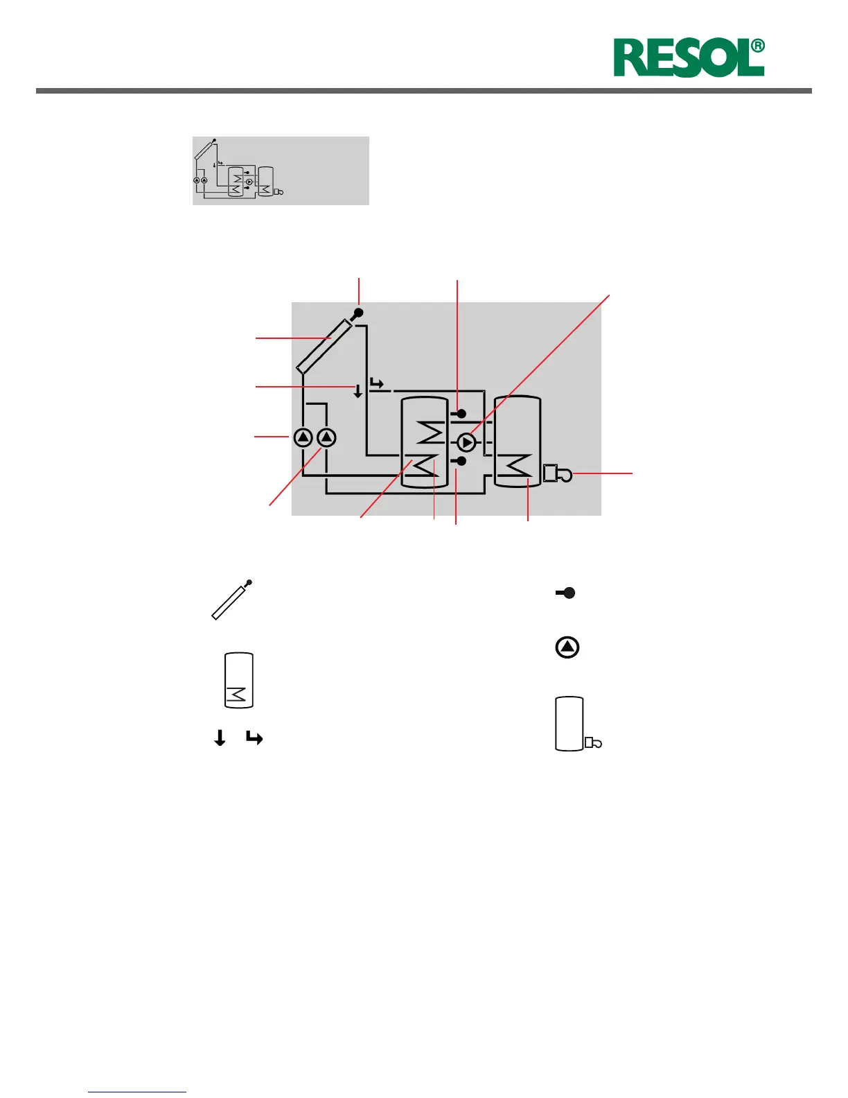
The system screen (active system layout) shows the system
selected on the controller. It consists of several system
component symbols, which are – depending on the current
status of the system – either flashing, permanently shown
or hidden.
3-way valve
The flow direction or the
actual switching position is
shown
System screen
system screen
green: everything OK
red/green flashing initialization phase
manual operation
red flashing: sensor fault
(sensor symbol is flashing quickly)
2.3 Flashing codes
LED flashing codes
System screen flashing codes
• Pumps are flashing when the corresponding relay is swit-
ched on
• Sensor symbols are flashing if the corresponding sensor
display channel is selected.
• Sensors are flashing quickly in the case of a sensor fault.
• Burner symbol is flashing if the backup heating is active
collector sensor
collector
valve
(heat dump)
tank
tank heat exchanger
tank sensor (top)
Pump
Tank
with heat exchanger
Backup heating
with burner symbol
Temperature sensor
Collector
with collector sensor
tank sensor
(bottom)
backup heating pump
solar pump
booster pump
backup heating with
burner symbol
heat exchanger
(heat dump)
 Loading...