D e lt a S o l
®
BS/3
© RESOL 10082_deltasol_bs/3.monus.indd
| 12
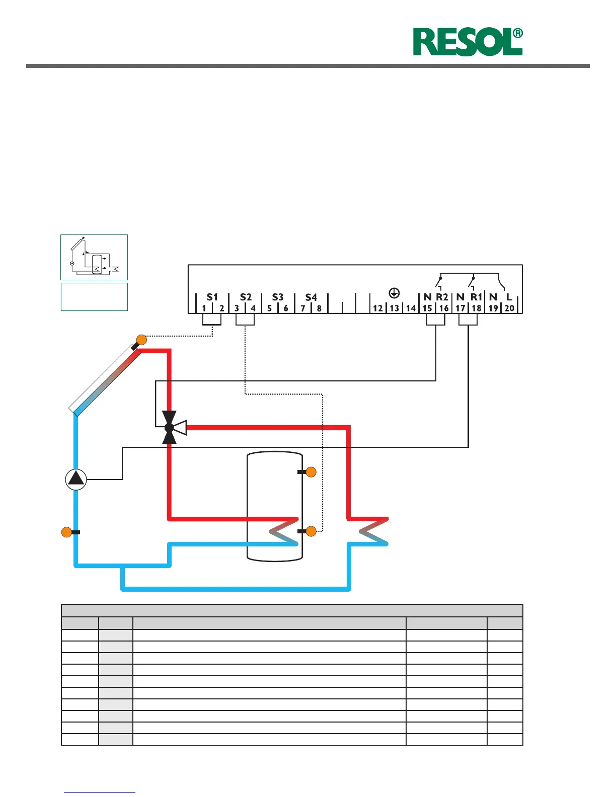
System layout 3
Arr 3
VBus
10
9
The controller calculates the temperature difference bet-
ween collector sensor S1 and tank sensor S2. If the diffe-
rence is larger than or identical to the adjusted switch-on
temperature difference (DT O), the solar pump will be
operated by relay 1, and the tank will be loaded until the
switch-off temperature difference (DT F) or the maximum
tank temperature (S MX) is reached.
If the maximum collector temperature (CMX) is reached, the
solar pump will be operated by relay 1 and the 3-way-valve
S1
S2
S4 / TR
R1
S3
R2
Display Channels
Channel Description Terminal Page
COL x Temperature collector S1 18
TST x Temperature tank S2 18
S3 x Temperature sensor 3 S3 18
S4 x Temperature sensor 4 S4 18
TR
x*
Temperature return sensor S4 18
h P1 x Operating hours R1 R1 19
h P2 x Operating hours R2 R2 19
kWh x* Heat quantity kWh - 19
MWh x* Heat quantity MWh - 19
TIME x Time - 16
will be operated by relay 2 in order to direct the surplus
energy to a heat dump. For security purpose this will be
carried out only if the tank temperature is below the non-
adjustable emergency shutdown of 200 °F.
Sensors S3 and S4 can optionally be connected for mea-
surement purposes.
If energy metering (OHQM) is activated, sensor S4 has to
be connected as return sensor.

 Loading...