D e lt a S o l
®
BS/3
© RESOL 10082_deltasol_bs/3.monus.indd
| 6
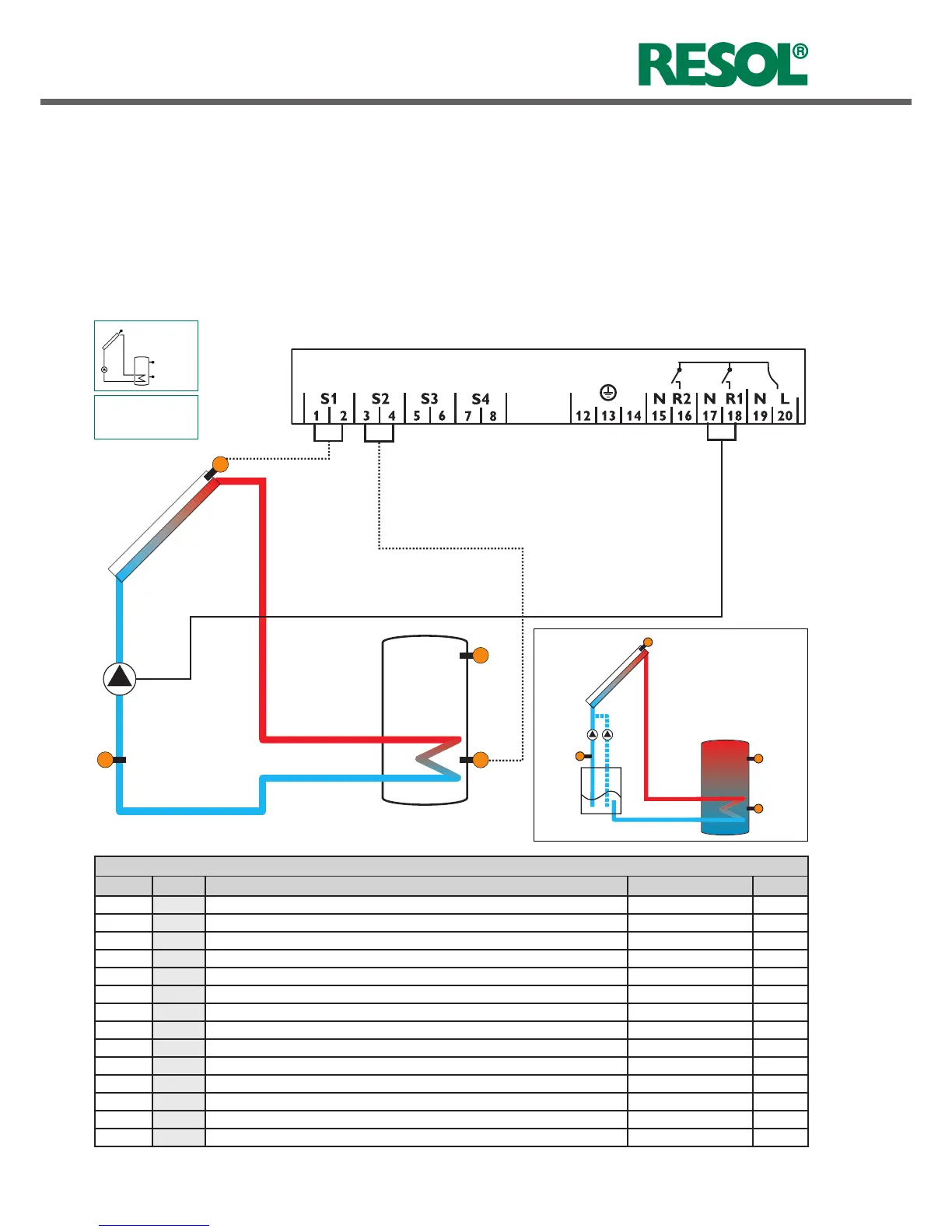
S1
S2
S4 / TR
System layout 1
The controller calculates the temperature difference bet-
ween collector sensor S1 and tank sensor S2. If the diffe-
rence is larger than or identical to the adjusted switch-on
temperature difference (DT O), the solar pump will be
operated by relay 1, and the tank will be loaded until the
switch-off temperature difference (DT F) or the maximum
tank temperature (S MX) is reached.
R1
Arr 1
S3
1.4 Terminal allocation in the different system layouts
Display Channels
Channel Description Terminal Page
INIT
x*
ODB initialization active - 19
FLL
x*
ODB filling time active - 19
STAB
x*
ODB stabilization in progress - 19
COL x Temperature collector S1 18
TST x Temperature tank S2 18
S3 x Temperature sensor 3 S3 18
S4 x Temperature sensor 4 S4 18
TR x* Temperature return sensor S4 18
hP x Operating hours R1 R1 19
hP1 x* Operating hours R1 (if OBST is activated) R1 19
hP2 x* Operating hours R2 (if OBST is activated) R2 19
kWh x* Heat quantity kWh - 19
MWh x* Heat quantity MWh - 19
TIME x Time - 16
Sensors S3 and S4 can optionally be connected for mea-
surement purposes.
If energy metering (OHQM) is activated, sensor S4 has to
be connected as return sensor.
If the drainback option (ODB) is activated, relay 2 can be
used to operate a booster pump by activating the booster
function (OBST).
S1
S3
S2
S4/TR
R1 R2
exemplary
Drainback system layout
(with booster pump)

 Loading...