DeltaSol
®
BS
© RESOL 06177 deltasol_bs1.monen.indd
7 |
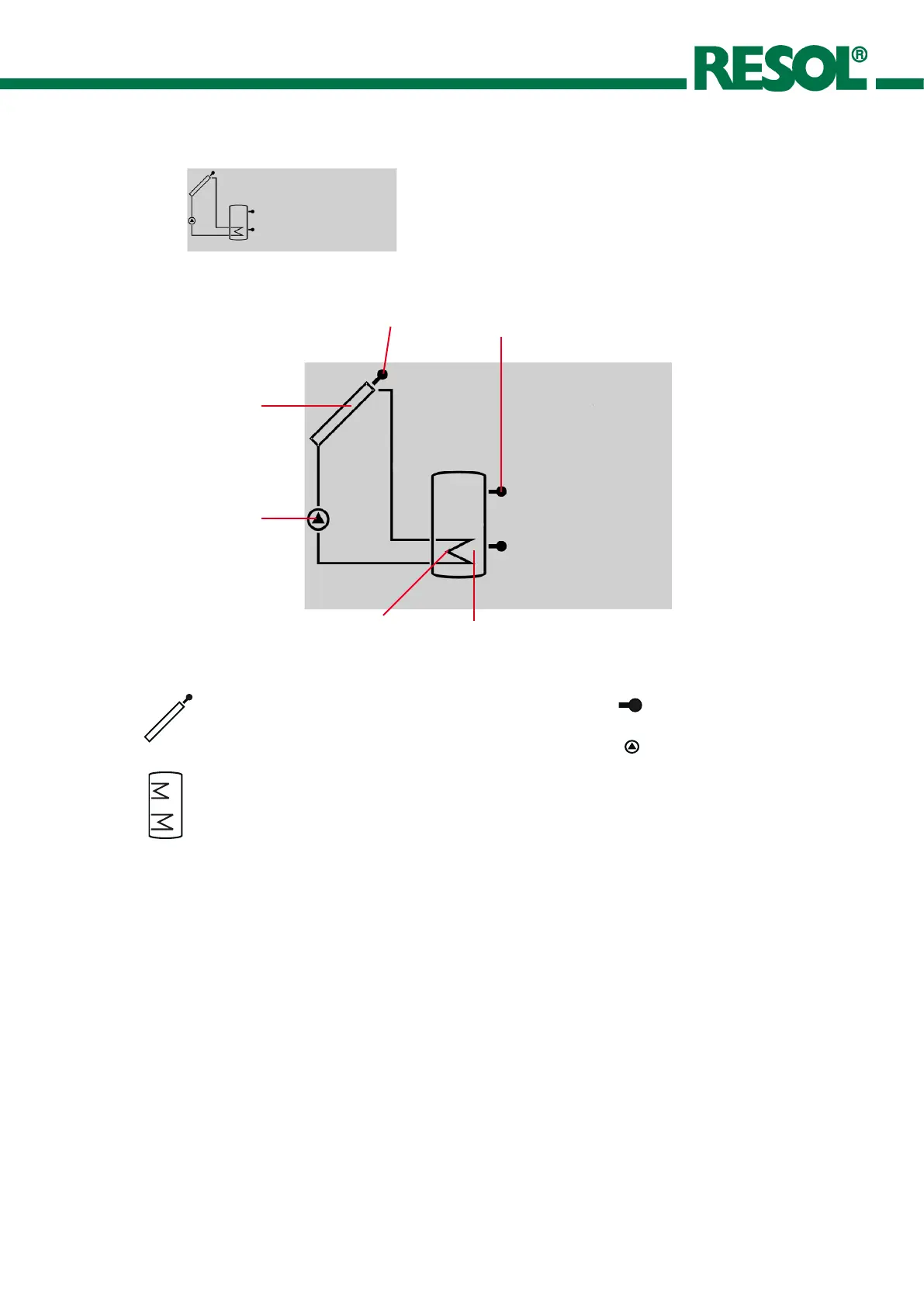
The system screen (active system scheme) shows the
schemes selected on the controller. It consists of several
system component symbols, which are - depending on the
current status of the system - either flashing, permanently
shown or hidden.
Sensor
Collector 1
Pumps
Tank
Tank heat exchanger
Sensor
Collector
with collector sensor
Pump
Tank 1
with heat exchanger
Temperature sensor
2.2.3 System screen
only system screen
Constantly green: everything all right
Red/green blinking: initialisation phase
manual operation
Red blinking: sensor defect
(sensor symbol is quickly blinking)
2.3 Blinking codes
2.3.2 LED blinking codes
2.3.1 System screen blinking codes
• Pumps are blinking during starting phase
• Sensors are blinking if the respective sensor-indication
channel is selected.
• Sensors are quickly blinking in case of sensor defect.
• Burner symbol is blinking if after-heating is activated.

 Loading...