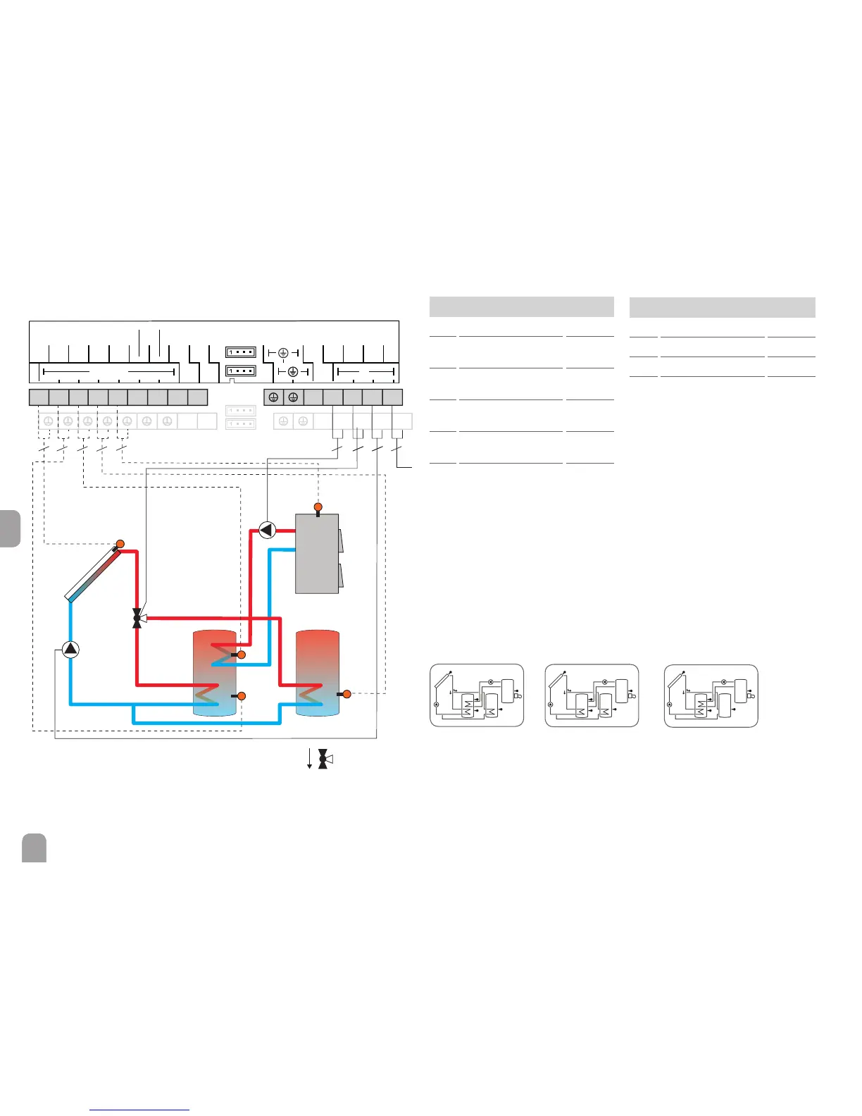
System 24: 2-store system with valve logic, 1 pump, 3 sensors and 3-port valve
The controller compares the temperature at sensor S1 to the temperatures at
sensors S2 and S4. If the measured temperature differences are higher than the
adjusted switch-on temperature differences, the pump (R1) will be activated and
the corresponding store will be loaded up to the adjusted store maximum or set
temperature respectively via the valve (R2). The priority logic effects prior loading
of store 1.
With another temperature differential function (S5 heat source/S3 heat sink), af-
terheating of the store with a solid fuel boiler can be carried out via another pump
(R3).
Hydraulic variant 1
Hydraulic variant 3Hydraulic variant 2
Sensors
S1 Temperature collector 1 / GND
S2 Temperature store
base
2 / GND
S3 Temperature store –
solid fuel boiler
3 / GND
S4 Temperature store
base
4 / GND
S5 Temperature
solid fuel boiler
5 / GND
S6 Free S6
Relay
R1 Solar pump R1 / N / PE
R2 Valve solar circuit R2 / N / PE
R3 Store loading pump R3 / N / PE
R4 Free R4 /R4
R1
S4
S1
S2
VBus
VBus
S5/V40
S4
S3
GND
S6
S7
Sensors
Relais
S2
S1
N
R3
R2
R1
L
R4
PWM A
0-10 V
PWM B
0-10 V
R4
N N N N
R3 R2 R1 L
1234
56789
10 11
S3
2
3332
2 2 3
R3
2
R2
S5

 Loading...