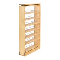
FIGURE 1
23-1/16"
21-1/8"
6-13/16"
32"
DIMEMSIONS ARE
"MINIMUM"
INSTALLATION TEMPLATE
ON REVERSE SIDE.
3. Locate the mounting holes with the template and afix the upper pivot support to the underside of the
cabinet top (see Figure 2) with four (4) 1/2" x #8 (F0808-26-2) oval head screws.
6. Adjust the upper shelf position by grasping and supporting the upper shelf positioner assembly while
loosening the locking screw. Rotate the positioner and shelf into alignment and securely tighten the
locking screw.
5. Insert the upper shaft assembly into the top end of the shaft. Loosely install the lock screw. Insert the
shaft/tray assembly into the bottom positioner. Extend the upper shaft assembly to engage the upper
pivot support (See Figure 2).
4. Working from bottom up, slide the upper shelf onto the shaft. Slide the upper positioner onto the shaft and
temporarily tighten the screw with the positioner approximately 15" from the bottom of the shaft. Slide the
bottom shelf onto the shaft.
2. Locate the mounting holes with the template (see reverse side) and afix the bottom positioner to the
cabinet floor with four (4) 3/4" x #8 (F1208-13-2) oval head screws. NOTE: Shaft locking screw must
face cabinet opening.
1. Insert shelf support in tray from bottom with keyway to rear of tray and position top shelf hub on top of
tray with keyway to rear of tray. Install three (3) 3/4" x #8 (M1812-251-2) self tapping pan head screws
through top hub into shelf support and tighten.
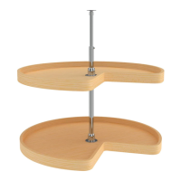
FIGURE 2
LOCKING SCREW
(M2405-409-2)
SHAFT LOCKING SCREW
(M2408-409-2)
UPPER PIVOT SUPPORT
(6000-91-2)
SHAFT
(6470-96-2208-26)
SHELF SUPPORT
(6470-07-2)
BOTTOM POSITIONER
(6260-95-2)
UPPER POSITIONER
(6260-95-2)
SHAFT LOCKING SCREW
(M2408-409-2)
UPPER SHAFT ASSEMBLY
(6470-93-0904-26)
24" - 32" K IDNE Y
INS T A L L A T ION INS T R UC T IO NS
W L S S E R IE S L A ZY S US A NS
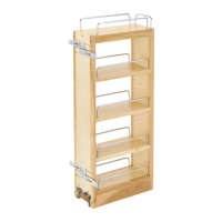
28"
DIMEMSIONS ARE
"MINIMUM"
5-1/16"
19-5/16"
17-11/16"
24"
DIMEMSIONS ARE
"MINIMUM"
2-11/16"
14-11/16"
14-15/16"
NOTE: The dimensions shown in Figure 1. are minimum.
© 2002 REV-A-SHELF, LLC
2409 Plantside Drive • Jeffersontown, Kentucky 40299 • 800-626-1126
www.rev-a-shelf.com
T-4WLS 802
http://www.kitchensource.com/lazy-susan/rv-4wls472-24-52.htm