ILLUSTRATED PARTS MANUALS
SERIES 7 SHREDDERS – 230v
DESKSIDE AND OFFICE MODELS
SECTION 3 – PRINTED CIRCUIT BOARD IN TOP COVER (ALL
MODELS)
Removal
1. Remove top cover away from machine as described in section 1.
2. Remove seven pozi-drive screws holding PCB to top cover. Lift
out the circuit board.
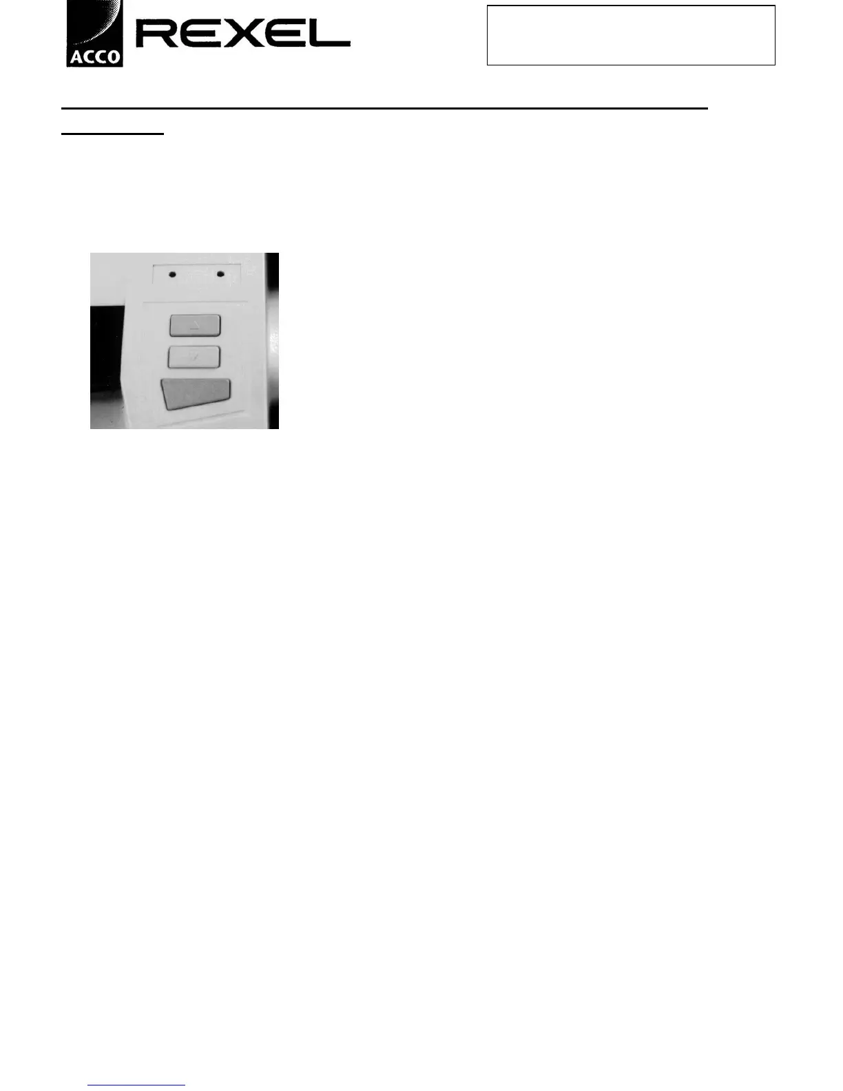
3. Note that removing the PCB exposes three switch mechanisms;
take care that these do not become displaced or lost. Positions are as
follows: -
rear…………………….green (start)
central………………….blue (reverse)
nearest front of lid……..red (stop)
Replacement
1. Ensuring that the three switch actuators are positioned correctly, place the PCB in position and fit
screws.
2. Replace top cover.
3. Test operation.
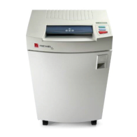
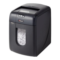
View of control buttons –
(1150 controls shown)