Do you have a question about the Rexroth Indramat Mannesmann DKC21.3 and is the answer not in the manual?
Describes the function of a roll feed to transport material under a press, cutter or stamper.
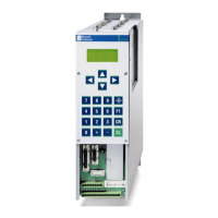
Lists the hardware components for a standard roll feed with ELC control.
Explains the ELC program sequence for roll feed applications, including 'Feed before Press' and 'Press before Feed' examples.
Details the programming procedures using the BTV04 operator terminal, including menu navigation and function keys.
Explains the main menu structure and navigation within the BTV04 for programming roll feeds.
Describes how to input feed length, speed, and velocity settings using the F1 function on the BTV04.
Explains how to input the actual and setpoint number of pieces using the F2 function.
Details setting outputs to control tools like the press before and after the feed.
Displays information from motor or measuring wheel encoders, including length and speed.
Allows checking the status of system inputs and outputs, and viewing freely-programmable I/Os.
Shows how free-use inputs are displayed and their status (switched on/off).
Explains how outputs and markers can be switched and queried in the user program.
Displays the status of markers 33 through 64, showing switched on/off states.
Displays the status of markers 65 through 99, showing switched on/off states.
Shows press stroke count and required feed time as a percentage of feed distance.
Allows pre-selection of operating modes and adjustment of display contrast.
Enables selection of operating modes in single steps for set-up and automatic modes.
Displays the currently programmed operating mode, such as automatic mode or feed leads.
Allows adjustment of display contrast and protection of parameters with a password.
Provides information about the drive, status messages, and warnings, automatically switching to a fault picture.
Allows complete programming and parametrization of the ELC control, protected by a password.
Sets the BTV language based on the ELC parameter B000.
Enables jogging and control of the automatic program via serial interface, reducing need for hardware inputs.
Configures the application settings and motion type for the roll feed.
Sets the feed constant in EGE, related to motor revolution or draw-off roll circumference.
Defines the gear ratio between the motor and the draw-off roll.
Sets the maximum material speed (EGE/sec) based on drive and amplifier power.
Configures the set-up speed in EGE/sec for travel speed in jog mode.
Sets the maximum bipolar acceleration symmetric for both directions (accel and decel).
Sets the switching threshold and output for position reached.
Monitors the position control loop and sets the maximum tolerable offset.
Monitors feed motion, terminating it and generating a fault message if the input signal fails.
Sets the maximum allowed offset (slip) between motor and measuring wheel encoders.
Defines the number of commands in task3 per NC cycle and task start settings.
Controls electrical ventilating and can be activated via an input if search pins are used.
Activates the measuring wheel mode for control, based on input status and parameter A100.
Sets the language preference for the BTV, as defined in ELC parameter B000.
Sets parity check and baud rate for serial communication.
Configures transmission deceleration time, error message sending, station number, and checksum.
Manages serial inputs/outputs, maximum cycle time, and handles communication errors.
Enables standard or serial system control and monitors cyclic transmission for warnings or errors.
Sets the motor turning direction (clockwise or counterclockwise).
Configures the encoder type for the measuring wheel, specifying incremental 5V square-wave signals.
Sets the position encoder type, distance-coded measuring system, motional direction, and absolute evaluation.
Sets the resolution for the measuring wheel encoder (lines/revolutions or lines/mm).
Defines the feed constant in EGE for the measuring wheel.
Sets the Kv factor, which relates voltage to speed, within a specified input range.
Lists parameters related to application setup, speed, acceleration, and monitoring.
Covers parameters for tasks, vectors, restart, override, and measuring wheel mode.
Details parameters for display settings, interface configuration, and analog outputs.
Lists parameters for motor polarity, encoders, homing, and reference settings.
Includes parameters for controller gains, time constants, and switching frequency.
Details the control voltage, interface, and power connections between BTV04 and DKC 21.3.
Provides a diagram of the Digital drive controller DKC 21.3's inputs and outputs, including parameter mapping.
Lists available firmware, software, drive controllers, motors, and connecting cables.
| Type | DKC21.3 |
|---|---|
| Category | Controller |
| Manufacturer | Rexroth Indramat Mannesmann |
| Voltage Supply | 24 V DC |
| Protection Class | IP20 |
| Operating Temperature | 0 to +50 °C |
| Storage Temperature | -20 to +70 °C |
| Relative Humidity | 5% to 95% (non-condensing) |