REYMSA COOLING TOWERS, INC.
www.reymsa.com
20
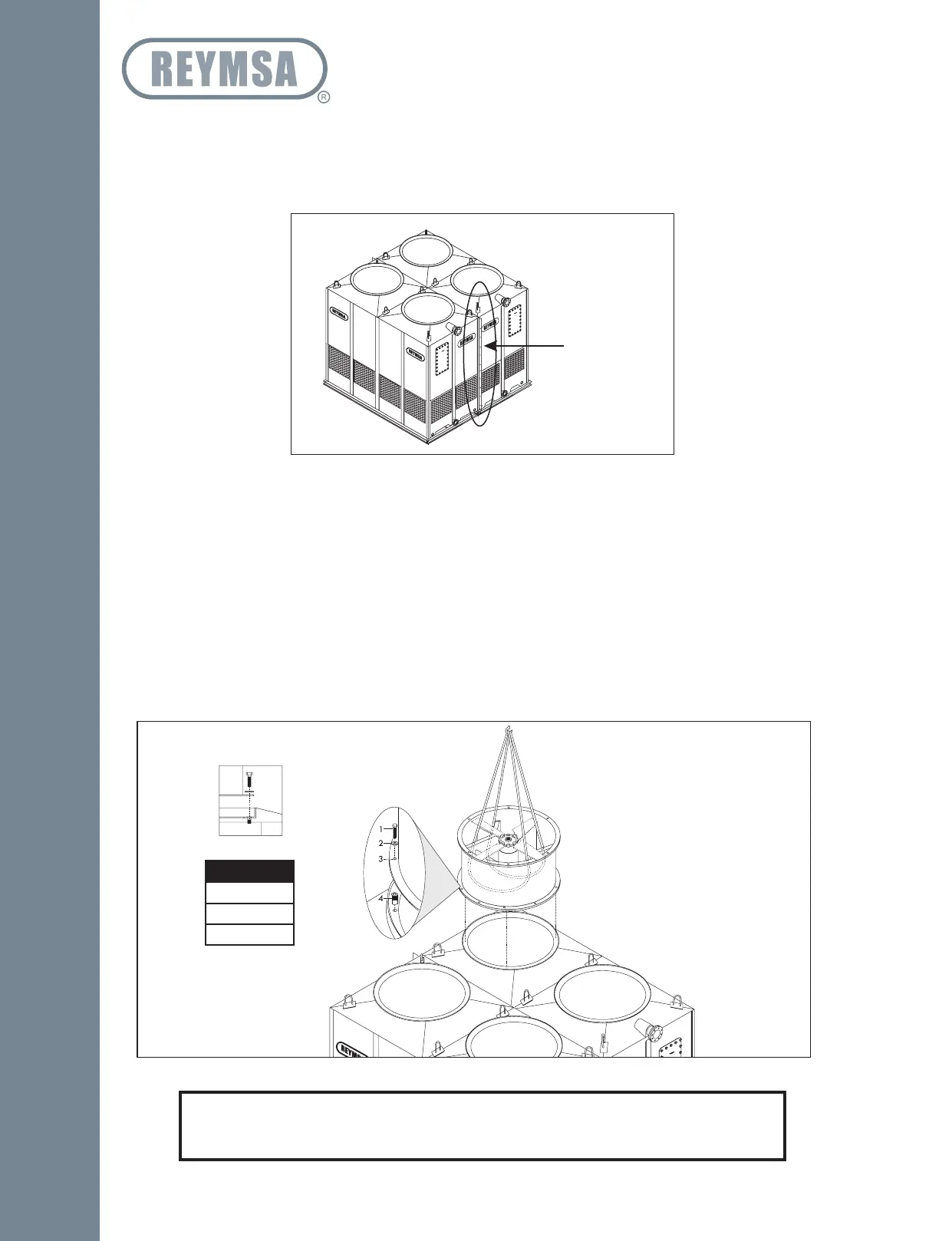
H. Place Section #2 (unitized body & basin) on top of the isolation pad and the base structure, and then
proceeds to bolt together the vertical flanges of Sections 1 & 2; use first the galvanized bolts and nuts
to join sections (supplied by REYMSA). Then replace the galvanized bolts with the stainless steel nut and
bolt sets supplied by REYMSA (see Figure A-44). Then bolt down and secure Tower Section #2 to the
structural base with stainless steel nut and bolt sets (supplied by others) as shown on Figure A-43.
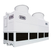
I. Remove fan guard.
J. Then cradle/straddle the fan support with the straps (as shown in Figure A-45) so you can lift the fan duct
with a crane and assemble it.
K. Identify each fan duct, they are labeled with a number on the inside of the lower edge. For a correct
installation, this number must match the number on the distribution manifold of the corresponding body
section. Place fan duct 1 on the corresponding receiving flange on top of body section 1 of the Tower;
make sure the bolt holes and the marks inside the fan duct and receiving flange are aligned (Figure A-41
and A-45). Secure it with the stainless steel nut and bolt sets supplied by REYMSA.
L. Continue to place fan duct 2 on top of body section 1, following the same instructions mentioned in
previous step. Follow the step I, J and K for the remaining fan ducts.
Figure A-45: Fan Duct installation for a Quadruple Fan Tower.
ASSEMBLY HOLES
1. 1/2” X 2.5” Bolt
2. 1/2” Flat Washer
3. 5/8 Hole
4. 1/2” Screw Insert
(Factory assembled)
RECESSED FLANGE
MODELS
RTU-1414
RTU-1616
RTU-1619
Figure A-44: Body section 2 installation for a Quadruple Fan Tower
Vertical flanges
NOTE
If your Tower is for a low sound application and it includes a fan adaptor please see
Section “A.7 LOW SOUND FAN COOLING TOWERS: FAN ADAPTORS”.
Installation