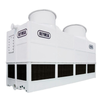
REYMSA COOLING TOWERS, INC.
www.reymsa.com
The
All-Fiberglass
Cooling Towers
27
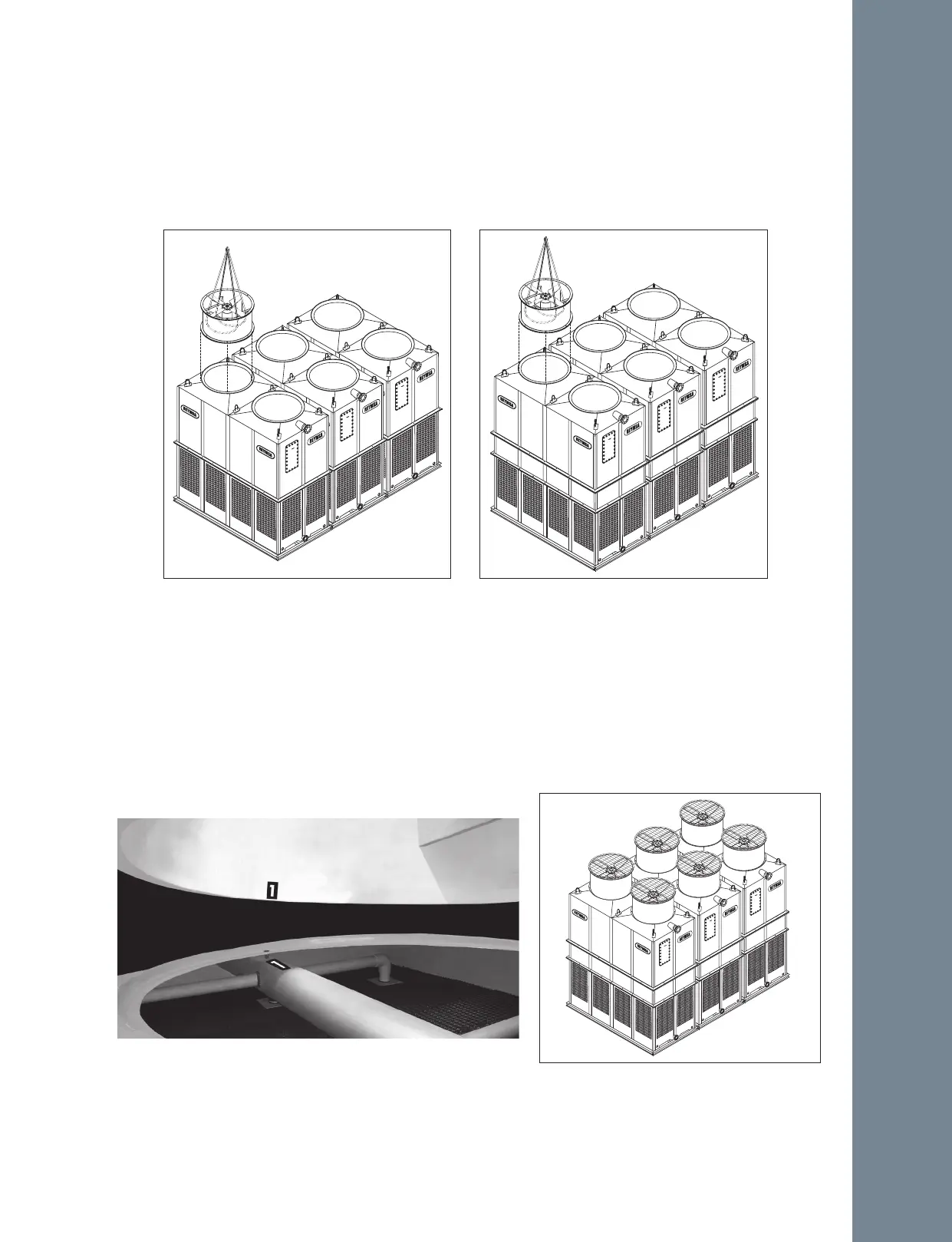
After all the modules have been installed, proceed assemble the fan ducts.
C. Remove fan guard from fan section.
D. Then cradle/straddle the fan support with the straps (as shown in figure A-63 and A-64) so you can lift
the fan duct with a crane and assemble it.
E. Identify each fan duct, they are labeled with a number on the inside of the lower edge. For a correct
installation, this number must match the number on the distribution manifold of the corresponding body
section. Now place fan duct 1 on the correspondent receiving flange on top of the Tower; make sure the
bolt holes and the marks inside the fan duct and the receiving flange are aligned (see Figure A-65).
Secure it with the stainless steel nut and bolt sets supplied by REYMSA.
F. Follow the same instructions to place the remaining fan ducts (see figure A-66).
Figure A-63: Fan Duct installation for a Modular
Tower (RTM-B-L)
Figure A-64: Fan Duct installation for a Modular
Tower (RTM-D-L)
Figure A-65: Fan Duct alignment for a Modular Tower
Figure A-66: Modular Tower installed by large
side arrangement (-L)
Installation