5
I-SCE (09-18) PN207697R9
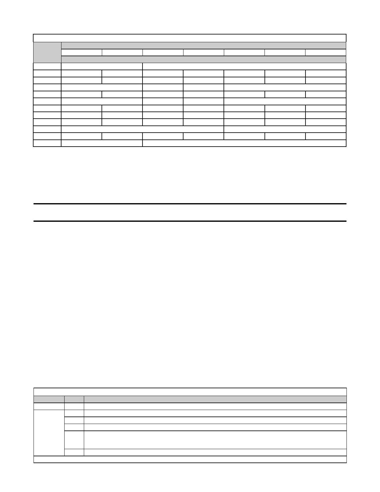
Table 1. Model SCE Dimensions
Dimension
Code from
Figure 2
Model
125 150 and 175 200 and 225 250 300 350 400
Inches ±1/8 (mm ±3)
A 32-1/4 (819) 35-1/4 (895)
B 25-1/4 (641) 30-3/4 (781) 36-1/4 (921) 43-1/2 (1105) 44-1/2 (1130) 50 (1270) 55-1/2 (1410)
D 15-1/4 (387) 20-3/4 (527) 26-1/4 (667) 33-1/2 (851) 34-1/2 (876) 40 (1016) 45-1/2 (1156)
E 8-1/8 (206) 10-3/4 (273) 9-3/4 (248) 10-3/4 (273)
F 16-1/4 (413) 21-3/4 (552) 27-1/4 (692) 34-1/2 (876) 35-1/2 (902) 41 (1041) 46-1/2 (1181)
G 7 (178) 10 (254) 9 (229) 10 (254)
H 17-3/4 (451) 23-1/4 (591) 28-3/4 (730) 36 (914) 37 (940) 42-1/2 (1080) 48 (1219)
J 17-3/8 (441) 22-7/8 (581) 28-3/8 (721) 35-5/8 (905) 38-5/8 (930) 42-1/8 (1070) 47-5/8 (1210)
K 17 (432) 18-3/8 (467) 17 (432) 16 (406) 17 (432) 18-3/8 (467) 17 (432)
L 1/2 (13) 3/4 (19)
M 40-1/4 (1022) 39 (991) 40-1/4 (1022) 39-1/4 (997) 40-1/4 (1022) 39 (991) 40-1/4 (1022)
N 27-3/4 (705) 30-3/4 (781)
UNCRATING/UNPACKING
The furnace is shipped completely-assembled. Immediately upon uncrating, check the gas specifications and electrical
characteristics of the unit to be sure that they agree with the gas and electric supply at the installation site.
Check the unit for any damage that may have been incurred during shipment. If damage is found, document the
damage with the transporting agency and immediately contact your distributor. If you are an authorized distributor,
follow the FOB freight policy procedures.
NOTE: After removing the shipping clips that fasten the unit to the crate, it is required that the
bolts that attach the shipping clips be reinstalled for support.
The bottom corners are fastened to the crate using angled shipping clips. Remove the bolts from the shipping clips
and remove the clips. Reinstall the bolts on the heater legs to support the corner leg and the heater bottom.
To protect the unit during shipping, blower models have special supports that must be removed before installation.
Remove the special supports as follows:
• Blower Support Legs: Remove the blower support legs and screws.
• Motor Shipping Block: Remove the wooden block located under the motor bracket. Find the two rubber pads
shipped in the instruction envelope. Place these pads on the ends of the motor bracket bolts.
• Motor Shipping Plate: Units equipped with motors of 1-1/2 HP or less have a metal shipping plate attached between
the motor and the blower housing. The shipping plate must be removed and the plate and screws discarded. on
a unit factory-equipped with an optional belt guard, the belt guard must be removed to reach the shipping plate.
Vent Terminal/Combustion Air Inlet Kit with Concentric Adapter Box
The concentric adapter box assembly in the venting/combustion air kit (option CC2 or CC6) is required on all
separated-combustion models. Ensure that the concentric adapter box carton is at the installation site (refer to parts
list in Table 6 or Table 8).
Shipped-Separate Parts
Some gas control options have parts that are either shipped loose—with the heater—or shipped separate. Before
beginning installation, ensure that any shipped-separate parts ordered are available at the site. Shipped-separate
options could include a shutoff valve, a condensate drain kit, a thermostat, a remote console, a disconnect switch, or
high-temperature vent sealing tape. Also, if your unit is equipped with any of the gas control options listed in Table
2, ensure that these parts are available at the job site.
Table 2. Shipped-Separate Parts for Gas Control Options
Application Option Part(s)
Heating
AG7
Thermostat (PN 48033)
Makeup air
AG3
Control switch (PN 29054)
AG8
Control switch (PN 29054); sensor and mixing tube (PN 48041)
AG9
Control switch (PN 29054); remote temperature selector (PN 48042); sensor and mixing tube (PN 48041)
AG15
&
AG16
Control switch (PN 29054); remote temperature selector (PN 115848); stage adder module (PN 115849); discharge
air sensor holder (PN 115850); discharge air sensor holder bracket (PN 213612); AG16 also includes temperature
display (PN 115852)
AG39
Remote temperature selector (PN 174849); temperature sensor (PN 133228); mixing tube (PN 90323)
NOTE: If an optional remote console is ordered, the control switch and temperature selector may be mounted on the console.
 Loading...