35
I-SCE (09-18) PN207697R9
Computer-Controlled Electronic Modulation Between 20–28% and 100% Firing Rate (Option AG40)
NOTE: Option AG40 (US Patent 6,109,255) is available only with natural gas and is not available
on size 350.
With option AG40, the furnace is equipped with a Maxitrol signal conditioner (see Figure 27) that receives an input
signal of either 4–20 milliamps or 0–10V from a customer-supplied control device such as a computer. With the dip
switches on the conditioner positioned to ON, the conditioner accepts a 4–20 milliamp signal. With the dip switches
on the conditioner positioned to OFF, the conditioner accepts a 0–10V signal. The conditioner converts the signal
to the 0–20V DC current required to control the modulating valve. The heater functions and is equipped in the same
way as option AG39 except that with computer control, the temperatures are selected through the software and
there is no temperature selector or duct sensor.
Refer to Table 17 for option AG40 pressure requirements and to Figure 29 for troubleshooting option AG40.
Combustion Air Pressure Switch Settings for Options AG39 and AG40: This uniquely-designed modulation
system requires combustion air pressure settings different from the standard system. Refer to Table 18 for the
approximate combustion air proving switch settings at sea-level operation.
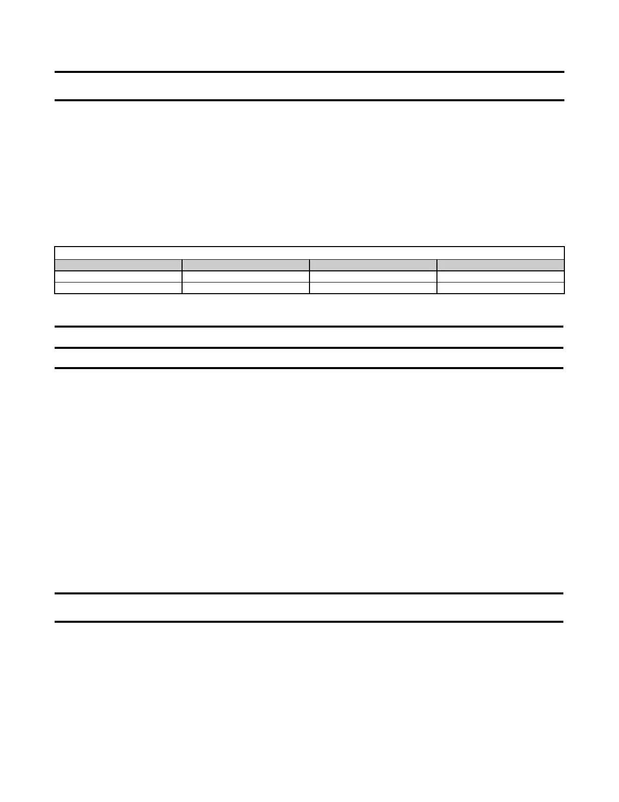
Table 18. Combustion Air Proving Switch Settings (Options AG39 and AG40)
Model Factory Setpoint Startup Cold Equilibrium
125–225 −1.00 IN WC (±0.02 IN WC) −1.30 IN WC (±0.20 IN WC) −1.05 IN WC (±0.10 IN WC)
250–300 and 400 −0.70 IN WC (±0.05 IN WC) −1.20 IN WC (±0.20 IN WC) −0.95 IN WC (±0.10 IN WC)
PILOT AND IGNITION SYSTEMS
⚠ WARNING ⚠
Due to high voltage on the pilot spark wire and pilot electrode, do not touch when energized.
Pilot: All pilots are vertical, target-type with a lint-free feature. Pilot flame should be approximately 1-1/4 inches
in length. Pilot gas pressure should be the same as the supply line pressure. Pilot gas is supplied through the
combination valve. Pilot gas flow is controlled by an adjustment screw located in the valve body. For maintenance,
refer to Burner Rack Maintenance and Cleaning Pilot and Burners.
Ignition System (Lockout): Natural gas units are equipped with a spark-ignited intermittent safety pilot system
(lockout) that shuts off pilot gas flow between heat cycles. Propane units (or as an option on natural gas units) require
a lockout device that stops gas flow to the pilot if the pilot fails to light in 120 seconds. The lockout device requires
manual set by interruption of the thermostat circuit. Refer to the wiring diagram provided with the unit for pilot system
identification and proper wiring. Pilot with lockout is option AH3. Spark pilot without lockout is option AH2.
Ignition Controller: As part of the intermittent safety pilot system, the ignition controller provides high voltage
spark to ignite pilot gas and also acts as the flame safety device. After ignition of the pilot gas, the ignition controller
electronically senses the pilot flame. A low voltage DC electrical signal is imposed on the separate metal probe in
the pilot assembly. The metal probe is electrically insulated from ground. The pilot flame acts as a conduction path
to ground, completing the DC circuit and proving pilot flame. Proper operation of the electronic spark ignition system
requires a minimum flame signal of 0.2 microamps DC, as measured by a microampmeter. With pilot flame proven,
the ignition controller energizes the main gas valve.
BURNERS, BURNER ORIFICES, AND CARRYOVER SYSTEM
NOTE: Natural gas units have a dual flash carryover system and do not require a carryover
orifice.
Burners: Individually-formed steel burners capable of operating on either natural or propane gas are used in this
heater. These burners have accurate, machine-formed ports to provide controlled flame stability and operation
without lifting or flashback. All burners are lightweight and factory-mounted in an assembly that permits all of the
burners to be removed as a unit for inspection or service.
Burner Orifices: Heaters are shipped with burner orifices of proper size and type for the specified gas. Refer to
Table 19 for burner and carryover orifice specifications.
 Loading...