34
I-SCE (09-18) PN207697R9
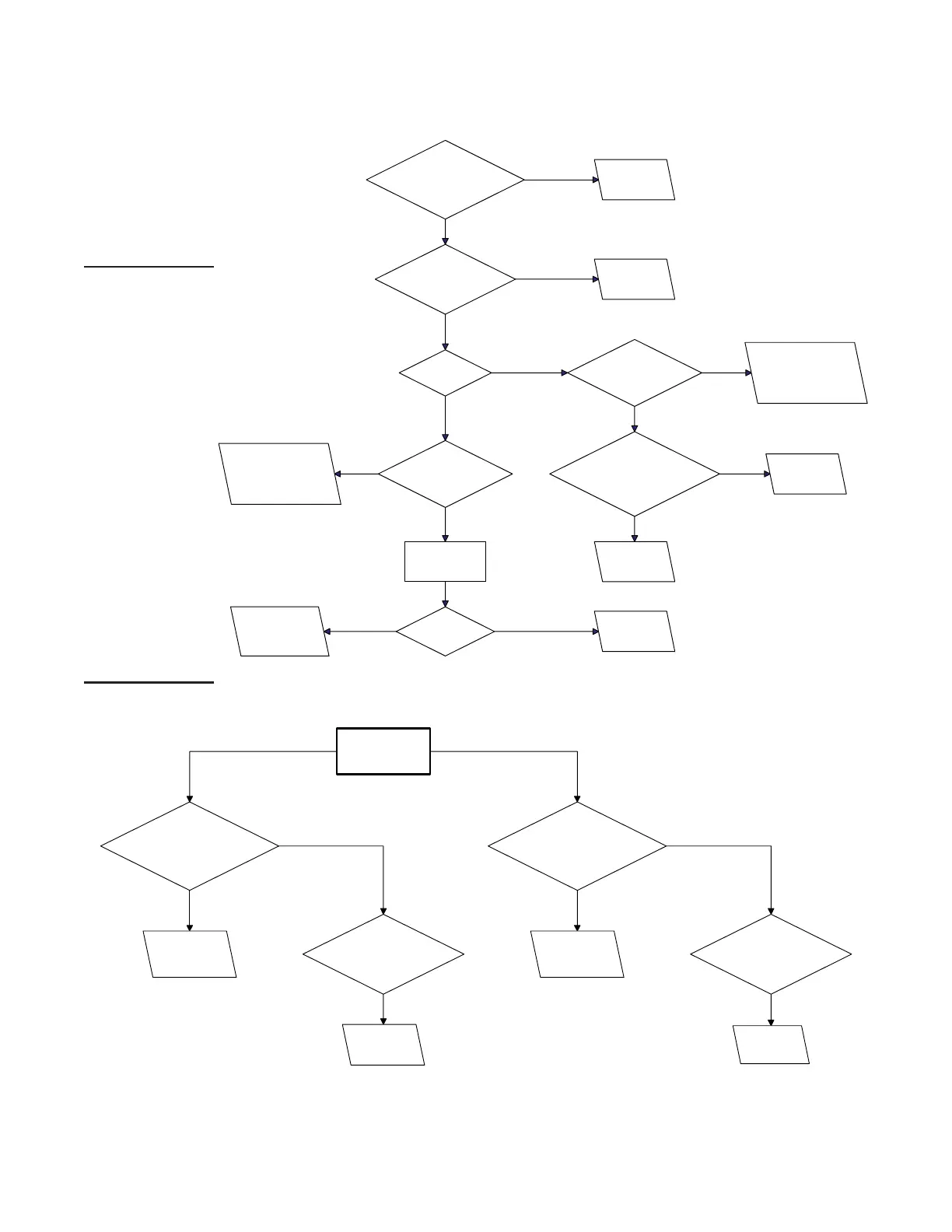
Figure 29. Troubleshooting Guide for Checking Bypass Combustion Air Damper Safety Circuit
on Units with Option AG39 or AG40
OPTIONAL ELECTRONIC MODULATION—CONTINUED
Electronic Modulation Between 20–28% and 100% Firing Rate (Option AG39)—Continued
Is there 24 volts
between Terminal 2 on #1
Time Delay Relay and
Terminal 7?
Go to
Troubleshooting
Chart for heater.
Is there 24 volts
between Terminal 84 and
Terminal 7?
Is the
damper open?
Is there voltage
between Terminal 88 and
Terminal 7?
Is there voltage
between Terminal 4 on
ignition permissive relay and
Terminal 7?
Replace #1 time
delay relay.
Replace ignition
permissive
relay.
Check combustion
damper lower end switch
adjustment. If necessary,
replace end switch.
Is there voltage
between Terminal 87 and
Terminal 7?
Check combustion
damper lower end switch
adjustment. Replace end
switch if necessary.
Place a jumper
across Terminal
86 and Terminal 7.
Did the
damper close?
Replace motor
run time delay
relay.
Replace combustion
damper gear motor.
Replace primary
manifold
pressure switch.
YES
NO
YES
NO
YES
NO
YES
NO
YES
NONO
YES
YESNO
Measure manifold
pressure
during burner cycling.
When the
manifold pressure is
BELOW 1.0" w.c., is there a steady
voltage between Terminal 95
and Terminal 7?
Replace secondary
manifold pressure
switch.
While the
burner is cycling, is
there a steady voltage
between Terminal 84 and
Terminal 2?
Replace the
primary manifold
pressure switch.
When the
manifold pressure is
ABOVE 1.5" w.c., is there a steady
voltage between Terminal 95
and Terminal 7?
Replace secondary
manifold pressure
switch.
Is there voltage
between Terminal 4 of the
ignition premissive relay and
Terminal 7?
Replace ignition
permissive
relay.
YES
NO
YES
NO
YES
NO
- Part 1:
burners are inoperative.
that 24 volts is
between Terminal 2
Terminal 7.
Instructions: For each step,
check to ensure that the wiring is not
defective and that the wiring connec-
tions
are secure.
- Part 2:
teady call for heat - burner cycles.
that 24 volts is available between Terminals 11 and 7 and Terminals 2 and 7.
 Loading...