33
I-SCE (09-18) PN207697R9
The gas supply (refer to pressure requirements in Table 17) connects to the single-stage gas valve. To compensate
for additional pressure loss through the modulating valve, the single-stage gas valve has a custom outlet pressure
setting higher than when it is used on a standard gas manifold. The pilot tubing connects to the pilot port on the
single-stage gas valve. When the valve receives a call for heat from the amplifier and pilot is established, gas flow
from the single-stage valve goes to both the modulating valve and the regulated lighter tube system. When the signal
from the amplifier to the modulating valve requires less-than-high fire operation, the modulating valve functions to
lessen the gas flow to the burner to reduce the input rate to that required to maintain the desired temperature. When
the input rate is reduced enough to decrease the gas pressure to 1.1 IN WC, the primary gas pressure switch in
the manifold activates the gear motor that controls the bypass damper in the venter/combustion air system. The
bypass damper opens to divert some of the incoming air directly into the flue duct and to reduce air flow through the
burner. Safety switches monitor the position of the bypass damper. When the gas pressure increases above 1.1
IN WC, the bypass damper closes.
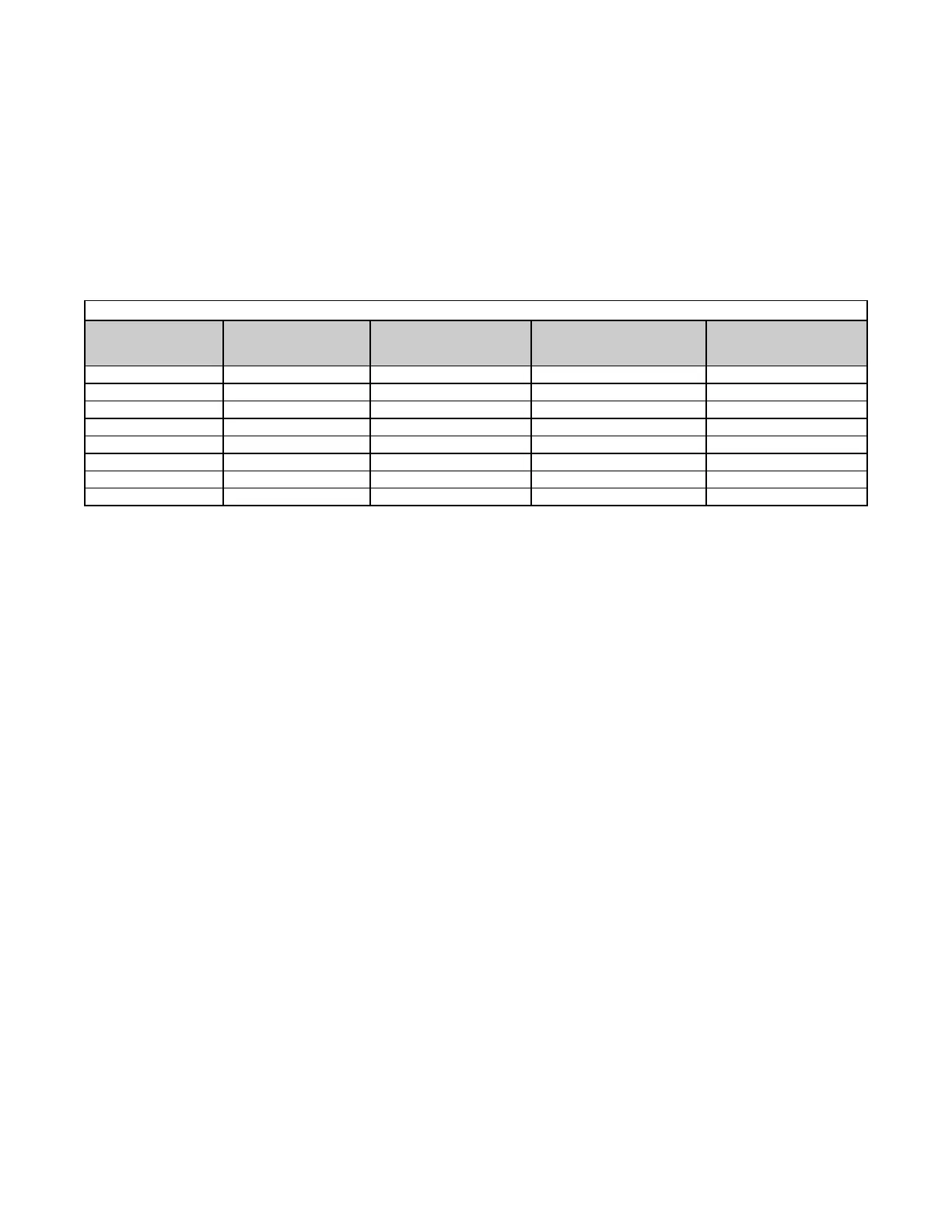
Table 17. Options AG39 and AG40 Pressure Requirements
Model Maximum Turndown MBH Input Range
Factory-Set Inlet Pressure
to Modulating Valve
(IN WC)
Gas Supply Pressure
Required
(IN WC)
125 20% 25–125 3.9 5.0
150 27% 40.3–150 3.7 5.0
175 23% 40.3–175 3.7 5.0
200 26% 51.8–200 3.9 5.0
225 23% 51.8–225 3.9 5.0
250 28% 69–250 4.0 5.0
300 23% 69–300 4.0 5.0
400 25% 100–400 4.4 6.0
Sensor Location: For the convenience of the installer, the duct temperature sensor is factory-installed in the cabinet
leg (see Figure 26). Although the sensor has a mixing tube, at this distance from the discharge it does not receive a
true mix, so the temperature read by the sensor will be slightly higher than the actual air entering the ductwork. The
system will provide comfort level heat if the selector is set slightly higher to compensate for this reading. If a direct
correlation of these two temperatures is required, move the duct sensor to a location in the ductwork about 10–12
feet (3–3.7 M) from the furnace discharge.
Wiring and Service: For wiring, consult the wiring diagram provided with the furnace. All wires in the electrical box
that connect to modulation controls must have a temperature rating of 150°C. This is a unique system which includes
custom-built components and custom settings. If service is required, follow the general guide in TROUBLESHOOTING
and the special troubleshooting guide shown in Figure 29.
 Loading...