EasyManua.ls Logo

Reznor SCE Series User Manual

Reznor SCE Series
48 pages
To Next Page IconTo Next Page
Page #1 background imageLoading...
Page #1 background image
Revision: I-SCE (09-18) PN207697R9
SEPARATED-COMBUSTION,
PACKAGED FURNACE/BLOWER,
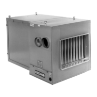
MODEL SCE
INSTALLATION/OPERATION/MAINTENANCE
 ⚠ WARNING ⚠ 
FIRE OR EXPLOSION HAZARD
Failure to follow safety warnings exactly could result in serious injury, death, or
property damage.
Be sure to read and understand the installation, operation, and service instructions
in this manual.
Improper installation, adjustment, alteration, service, or maintenance can cause serious
injury, death, or property damage.
Do not store or use gasoline or other flammable vapors and liquids in the vicinity of
this or any other appliance.
WHAT TO DO IF YOU SMELL GAS
Do not try to light any appliance.
Do not touch any electrical switch; do not use any phone in your building.
Leave the building immediately.
Immediately call your gas supplier from a phone remote from the building. Follow the
gas suppliers instructions.
If you cannot reach your gas supplier, call the fire department.
Installation and service must be performed by a qualified installer, service agency, or
the gas supplier.
DO NOT DESTROY. PLEASE READ CAREFULLY. KEEP IN A SAFE PLACE FOR FUTURE REFERENCE.
Supersedes: I-SCE (5-15) PN207697Rev8
TABLE OF CONTENTS
IMPORTANT SAFETY INFORMATION .................................................................. 2
GENERAL INFORMATION ............................................................................ 3
Installation Codes ................................................................................. 3
Special Installations (Aircraft Hangars/Garages) .......................................................... 3
Warranty ........................................................................................ 4
INSTALLATION ..................................................................................... 4
Dimensions ...................................................................................... 4
Uncrating/Unpacking ............................................................................... 5
Clearances ....................................................................................... 6
Location ......................................................................................... 6
Weights ......................................................................................... 6
Suspension ...................................................................................... 6
Mounting ........................................................................................ 7

Table of Contents

Questions and Answers:

Reznor SCE Series Specifications

General IconGeneral
Fuel TypeNatural Gas or Propane
Ignition TypeDirect Spark Ignition
Motor TypePSC or ECM
Heat Output Range30, 000 - 400, 000 BTU/hr
VentingSeparated Combustion
Gas Connection Size1/2" or 3/4" NPT
EfficiencyUp to 82% Thermal Efficiency

Summary

GENERAL INFORMATION

INSTALLATION CODES

Specifies installation standards and codes for units, including references to National Fuel Gas Code.

MODEL SCE UNIT HEATER

Description of the Model SCE unit heater, its design-certified status, and application.

INSTALLATION

SPECIAL INSTALLATIONS (AIRCRAFT HANGARS/GARAGES)

Guidelines for installing units in aircraft hangars and garages per relevant standards.

WARRANTY

Information on warranty conditions and terms that may void the warranty.

DIMENSIONS

Provides dimensional data for Model SCE unit heaters based on model size.

UNCRATING/UNPACKING

Instructions for safely uncrating and unpacking the unit, checking for damage.

Shipped-Separate Parts

Lists components shipped separately for specific gas control options.

CLEARANCES

Specifies minimum clearance requirements to combustibles for safety.

LOCATION

Guidance on optimal placement for unit heater performance and airflow.

WEIGHTS

Lists unit weights based on model size for structural support considerations.

SUSPENSION

Details methods for suspending the unit, emphasizing the need for it to be level.

MOUNTING

Describes required support locations and methods for unit mounting.

DUCT CONNECTIONS

Requirements and Suggestions for Connecting and Installing Ducts

Guidelines on ductwork type, material, structure, and installation for optimal performance.

VENTING AND COMBUSTION AIR

Venting Options

Details requirements for vent and combustion air systems, including specific kits.

Hazards of Chlorine

Warns about the dangers of chlorine in atmospheres for separated-combustion units.

Specific Venting Requirements: Piping

Outlines requirements for vent and combustion air piping, including lengths and diameters.

Specific Venting Requirements: Joints and Sealing

Provides instructions for sealing various vent pipe joints using sealant and screws.

Specific Venting Requirements: Support

Details requirements for supporting vent and combustion air piping to prevent stress.

Specific Venting Requirements: Clearance

Specifies clearance requirements for vent pipes from combustible materials.

Specific Venting Requirements: Concentric Adapter Box

Explains the use and installation of the concentric adapter box for venting.

Specific Venting Requirements: Concentric Adapter Box Pipe Connections

Details pipe connections for the concentric adapter box based on pipe size.

VENTING OPTIONS

Horizontal Vent Terminal/Combustion Air Package Kit (Option CC6)

Installation instructions for the horizontal venting kit, including parts and procedures.

Option CC6 Installation Instructions

Step-by-step guide for installing the CC6 horizontal vent kit.

Vertical Vent Terminal/Combustion Air Package Kit (Option CC2)

Installation instructions for the vertical venting kit, including parts and procedures.

Option CC2 Installation Instructions

Step-by-step guide for installing the CC2 vertical vent kit.

GAS PIPING AND PRESSURES

Pressure Testing Gas Supply Piping-Continued

Details procedures for testing gas supply piping for leaks and proper pressure.

Gas Connections

Illustrates and specifies gas connection sizes and requirements for natural and propane gas.

Sizing Gas Supply Lines

Provides guidance and tables for sizing gas supply lines based on flow rate and length.

Manifold or Orifice (Valve Outlet) Pressure Settings

Explains manifold pressure settings for natural and propane gas and associated warnings.

ELECTRICAL SUPPLY AND CONNECTIONS

Optional Single Stage Thermostat

Information on optional single-stage thermostat wiring and installation.

Disconnect Switch

Notes on the installation and requirements for a disconnect switch.

Optional Two Stage Thermostat

Information on optional two-stage thermostat wiring and installation.

CONTROL THERMOSTAT

Instructions for installing and setting the thermostat.

COMBUSTION AIR PROVING SWITCH

Details the function and settings of the combustion air proving switch.

BLOWER FAN CONTROL

Explains how the blower fan is controlled, including time delays.

LIMIT CONTROL

Describes the function of the limit control in interrupting electric supply.

MOTOR LOAD AND AMPS

Guidance on checking motor load and amp ratings, and FLA tables.

BELTS, BLOWERS, AND DRIVES

Instructions for checking and adjusting belt tension for motor and blower longevity.

Adjusting Blower Speed

Procedures for adjusting blower speed for optimal outlet temperature and performance.

Blower Rotation

How to change blower rotation on single/three-phase motors by rewiring.

Optional Variable Frequency Drive

Information on installing and programming the VFD option for variable speed control.

OPERATING VALVE

Details the function and safety aspects of the operating gas valve.

OPTIONAL TWO-STAGE OPERATION—HEATING ONLY APPLICATION

Describes two-stage heating operation with a gas control valve and thermostat.

OPTIONAL TWO-STAGE OPERATION—MAKEUP AIR APPLICATION

Explains two-stage makeup air operation controlled by a ductstat.

OPTIONAL ELECTRONIC MODULATION

Covers electronic modulation for heating and makeup air applications.

Computer-Controlled Electronic Modulation Between 50% and 100% Firing Rate (Option AG21)

Details computer-controlled modulation using a signal conditioner.

Sensor Location

Guidance on optimal placement of the duct temperature sensor for accurate readings.

Wiring and Service

Refers to wiring diagrams and service procedures for modulation controls.

Troubleshooting Guide for Checking Bypass Combustion Air Damper Safety Circuit

A guide for troubleshooting the bypass combustion air damper safety circuit.

PILOT AND IGNITION SYSTEMS

BURNERS, BURNER ORIFICES, AND CARRYOVER SYSTEM

Details the components and specifications of burners, orifices, and carryover systems.

BURNER AIR SHUTTERS

Instructions for adjusting burner air shutters for optimal flame and combustion.

OPTIONAL EQUIPMENT

OPTIONAL CONDENSATION DRAIN FOR DUCT FURNACES

Instructions for installing and maintaining the condensate drain option.

OPTIONAL DAMPERS AND CONTROLS

Information on optional damper and control accessories.

OPTIONAL FILTER RACK AND FILTERS

Specifications and arrangements for optional filter racks and filters.

INSTALLATION AND STARTUP CHECKLISTS

PRE-STARTUP CHECKLIST

Detailed checks before initial unit startup, covering installation and electrical aspects.

STARTUP CHECKLIST

Procedures for verifying correct furnace operation during startup sequence.

POST-STARTUP CHECKLIST

Final checks after the unit has been started and operated, including flame and pressure.

SERVICE AND MAINTENANCE

OPERATING GAS VALVE MAINTENANCE

Procedures for checking and maintaining the operating gas valve for safety.

VENT/COMBUSTION AIR SYSTEM MAINTENANCE

Instructions for maintaining the vent and combustion air system, checking for leaks.

BURNER RACK MAINTENANCE

Steps for removing, cleaning, and reinstalling the burner rack assembly.

CLEANING PILOT AND BURNERS

Procedures for cleaning pilot assemblies and burners for optimal flame.

SPARK IGNITION SYSTEM MAINTENANCE

Maintenance procedures for the spark ignition system and controller.

VENTOR MOTOR MAINTENANCE

Notes on maintenance for venter motors, emphasizing permanent lubrication.

AIR CIRCULATION SYSTEM MAINTENANCE

Maintenance for the blower pulley and belt system, checking tension and alignment.

LIMIT CONTROL CHECK

Procedure to check the operation of the limit control by blocking air supply.

TROUBLESHOOTING

INSTALLATION RECORD

Related product manuals