15
I-SCE (09-18) PN207697R9
c. Allow downward pitch of 1/4-inch per foot (6 mm per 305 mm) for condensate drain.
NOTE: Local codes supersede all provisions in these instructions and in National Fuel Gas
Code Z223.1.
d. Ensure that distance of vent terminal from adjacent public walkways and buildings and window and building
openings complies with local codes. Absent any local codes, distance must comply with National Fuel Gas
Code Z223.1.
NOTE: Products of combustion can cause discoloration of some building finishes and deterio-
ration of masonry materials. A clear silicone sealant normally used to protect concrete drive-
ways may be used to protect masonry materials from discoloration and deterioration. If discol-
oration is an esthetic problem relocate the vent or install a vertical vent.
e. Refer to Table 7 to ensure that location complies with minimum clearance requirements.
⚠ DANGER ⚠
• To prevent combustion products from entering the occupied space, all vent terminals must be
positioned or located away from fresh air intakes, doors, and windows. Failure to comply could
result in severe personal injury or death and/or property damage.
• Consider local snow depth conditions. The vent must be at least 6 inches (152 mm) above the
anticipated snow depth.
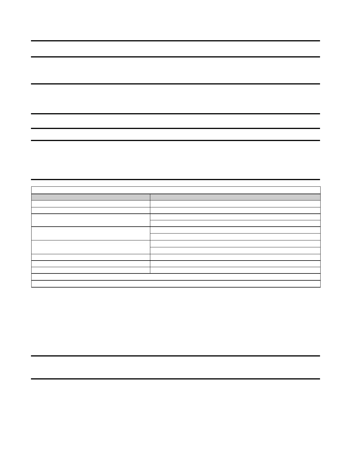
Table 7. Minimum Clearance Requirements for Horizontal Vent Terminal
Component/Structure Minimum Clearance, All Directions Unless Specified (Feet (Meters))
Forced air inlet within 10 feet (3.1 M)*
3 (0.9) above
Combustion air inlet of another appliance 6 (1.8)
Any building opening (door, window, or gravity air inlet)
4 (1.2) horizontal and below
1 (305) above
Gas meter,** electric meter, and relief equipment
US: 4 (1.2) horizontal
Canada: 6 (1.8) horizontal
Gas regulator**
US: 3 (0.9) horizontal
Canada: 6 (1.8) horizontal
Adjoining building or parapet 6 (1.8)
Adjacent public walkway 7 (2.1) above
Grade (ground level) 3 (0.9) above
*Does not apply to the inlet of a direct vent appliance.
**Do not terminate the vent directly above a gas meter or service regulator.
2. Install vent pipe and combustion air pipe runs:
a. Connect piping to heater in accordance with specifications listed above in Specific Venting Requirements:
Piping and Specific Venting Requirements: Venter Outlet and Combustion Air Inlet Connections.
b. Seal all joints in accordance with specifications listed above in Specific Venting Requirements: Joints and
Sealing. Due to high temperature considerations, do not enclose exhaust pipe or place pipe closer than 6
inches (152 mm) to combustible material.
c. Extend piping runs close to wall location selected in step 1 and support piping in accordance with specifications
listed above in Specific Venting Requirements: Support.
NOTE: The larger diameter combustion air pipe serves as clearance for the vent pipe on non-
combustible construction. A thimble may be required depending on wall construction and/or
local codes.
3. Cut hole through outside wall for combustion air pipe.
a. Ensure that outside wall construction thickness is between 1 inch (25 mm) minimum and 48 inches (1143
mm) maximum.
b. Ensure that hole accommodates 8-inch (203-mm) combustion air pipe.
 Loading...