16
I-SCE (09-18) PN207697R9
VENTING OPTIONS—CONTINUED
Option CC6 Installation Instructions—Continued
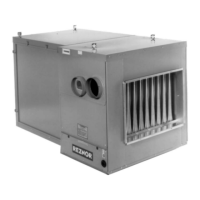
4. Connect concentric adapter box:
a. Refer to Figure 14 to attach brackets to box.
b. Connect outside portion of combustion air pipe to box. Determine length by measuring bracket length from
box to wall plus wall thickness and plus 2 inches (51 mm). Inlet air pipe should extend beyond outside wall
approximately 2 inches (51 mm).
c. Secure inlet air pipe to collar of concentric adapter using sheet metal screws and seal.
d. Refer to Figure 14 to attach concentric adapter box brackets to wall
e. Insert combustion air pipe through wall and caulk or flash inlet air pipe on outside. Flashing is field-supplied.
5. Install air inlet guard:
a. Position air inlet guard over end of combustion air pipe in accordance with Figure 15.
b. Secure air inlet guard to inlet air pipe using four 1/2-inch-long screws provided.
NOTE: If vent pipe is inserted from outside, the exhaust cap may be attached before the double-
wall vent pipe is installed. If cap is attached first, ensure that the baffle strips are positioned cor-
rectly when attaching the vent terminal pipe to the vent run (refer to step 6d below).
6. Install double-wall terminal vent pipe:
NOTE: The length of the vent pipe is determined by the installation within maximum and mini-
mum requirements. The vent pipe extending through the box and the inlet air pipe must be one
piece of double-wall vent pipe without joints.
a. Refer to Figure 15 to determine lengths of each pipe segment and to calculate total length required. Transi-
tion to single-wall or Category III vent pipe run must be made maximum of 6 inches (152 mm) from heater
side of box.
b. Ensure that double-wall terminal vent pipe is in proper direction and slide end of pipe through box. Position
pipe so that it will extend between 16–24 inches (406–610 mm) past end of combustion air pipe and no more
than 6 inches (152 mm) out of box toward heater.
c. Attach 5-inch double-wall vent pipe to 6- or 7-inch single-wall or Category III vent pipe run using tapered
reducer (see Figure 9).
d. Ensure that exhaust cap is aligned so that its baffle strips are positioned on horizontal and vertical center lines
(see Figure 15). Install cap in accordance with Figure 8.
e. Ensure that double-wall section of vent pipe has slight downward drop of 1/4-inch per foot (6 mm per 305 mm)
toward vent terminal end.
f. Seal vent pipe using silicone sealant. Completely seal circumference of pipe at opening of box.
Figure 14. Concentric Adapter Box Brackets
 Loading...