44
I-SCE (09-18) PN207697R9
CLEANING PILOT AND BURNERS—CONTINUED
• After the pilot is cleaned, blow away any dirt using compressed air.
• Clean the main burners and burner orifices using compressed air.
⚠ CAUTION ⚠
When cleaning burner ports, do not use anything that might change the port size.
• Use an air nozzle to blow out scale and dust accumulation from the burner ports. Alternate with blowing compressed
air through the burner ports and then through the venturi. Use a fine wire to dislodge any stubborn particles from
the burner ports.
• Clean the burner rack carryover systems with air pressure.
SPARK IGNITION SYSTEM MAINTENANCE
The ignition controller provides the high voltage spark to ignite the pilot service and also acts as the flame safety
device. After ignition of pilot gas, the controller electronically senses pilot flame. A separate solid metal probe in
the pilot burner assembly is used to sense the flame. A low voltage DC electrical signal is imposed on the metal
probe, which is electrically-insulated from ground. Proper operation of the electronic spark ignition system requires
a minimum flame signal of 0.2 microamps DC. When the pilot flame impinges on the sensing probe, the flame acts
as a conduction path to ground. This completes the DC circuit; the ignition controller responds by energizing the
main gas valve.
If no spark occurs, check the following:
⚠ WARNING ⚠
Due to high voltage on pilot spark wire and pilot electrode, do not touch when energized.
NOTE: When checking for spark with the pilot burner assembly removed from the burner rack,
the pilot assembly must be grounded to the heater for proper spark.
a. Using microampmeter, measure voltage between blue and white terminals (non-lockout type pilot) and between
terminals 2 and 5 (lockout type pilot) on ignition controller. Voltage should be at least 20 volts and no higher
than 32 volts. Refer to TROUBLESHOOTING if no voltage is observed.
b. Check for short to ground in high tension lead and/or ceramic insulator.
c. Verify that pilot spark gap (see Figure 37) is approximately 0.100 inch (2.5 mm).
If the above conditions are normal and no spark occurs, replace the ignition controller.
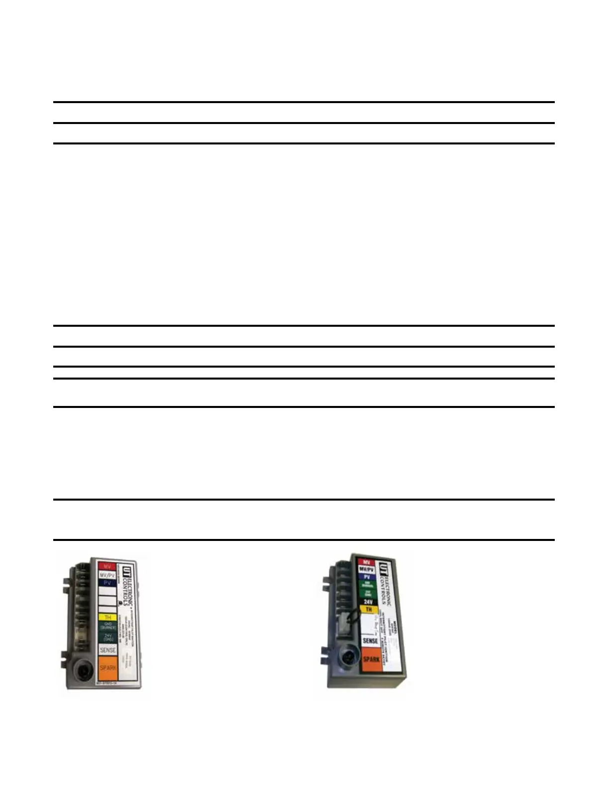
NOTE: If replacing an earlier model of ignition controller (see Figure 38), order a replacement
kit (PN 257472 for a unit with recycling gas control option AH2 or PN 257473 for a unit with gas
control with lockout option AH3). Option codes are listed on the unit wiring diagram.controllers.
IGNITION CONTROLLER WITH
LOCKOUT FOR GAS CONTROL
OPTION AH3, UTEC MODEL 1003-514
(PN 257010): REPLACE WITH
REPLACEMENT KIT (PN 257473)
RECYCLING IGNITION CONTROLLER
FOR GAS CONTROL OPTION AH2,
UTEC MODEL 1003-638A
(PN 257009): REPLACE WITH
REPLACEMENT KIT (PN 257472)
Figure 38. Obsolete Ignition Controllers
 Loading...