21
I-SCE (09-18) PN207697R9
b. Ensure that double-wall terminal vent pipe is in proper direction and slide end of pipe into box and out through
combustion air pipe. Position vent pipe to lengths determined above.
NOTE: The double-wall vent pipe does not attach to the box. The installer must provide support.
c. Connect double-wall vent pipe to single-wall or Category III vent pipe run using tapered reducer (see Figure 9).
d. Seal vent pipe using silicone sealant. Completely seal circumference of pipe at opening of box.
6. Install combustion air inlet and exhaust vent terminal:
a. On outside, slide combustion air inlet over vent pipe and fasten collar to combustion air pipe using sheet metal
screws (see Figure 19).
b. Using silicone sealant, seal opening at top between vent pipe and combustion air inlet to prevent water leakage.
c. Install exhaust vent terminal (see Figure 19) in accordance with Figure 8.
d. Install indoor combustion air pipe. If using 6-inch piping, secure single-wall combustion air pipe run to collar
on concentric adapter box using sheet metal screws. If using 7-inch piping (sizes 200–400), install tapered
enlarger as shown in Figure 11.
e. Seal pipe joints with tape or sealant.
7. Verify compliance with Figure 17 and with all specific venting requirements listed above.
GAS PIPING AND PRESSURES
⚠ WARNING ⚠
This appliance is equipped for a maximum gas supply pressure of 1/2 psi, 3.5 kPa, or 14 IN WC.
Supply pressures higher than 1/2 psi require installation of an additional service regulator external
to the unit.
Pressure Testing Gas Supply Piping
• To test piping when gas supply pressure is above 1/2 psi: Disconnect the heater and manual valve from the
gas supply line that is to be tested. Cap or plug the supply line.
• To test piping when gas supply pressure is below 1/2 psi: Before testing, close the manual valve on the heater.
⚠ WARNING ⚠
Manifold gas pressure must never exceed 3.5 IN WC for natural gas or 10 IN WC for propane gas.
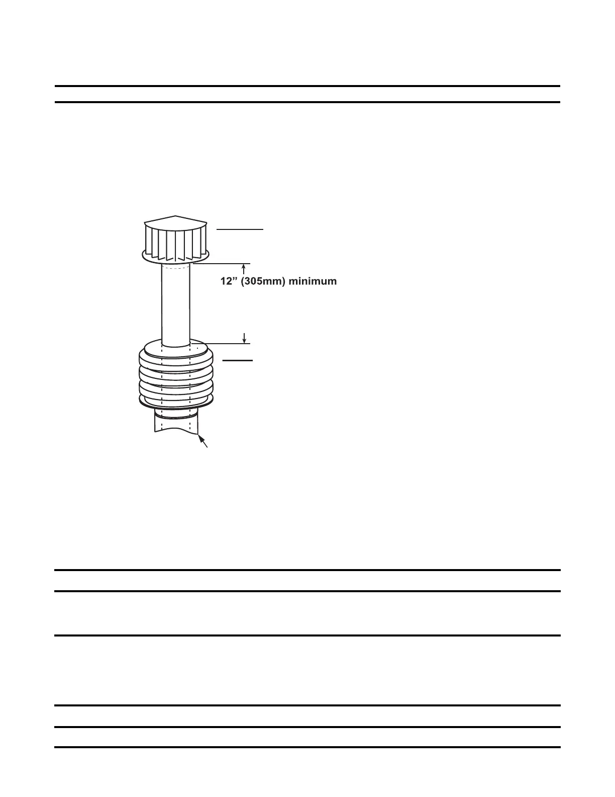
Figure 19. Combustion Air Inlet and Vent Terminal Installation
SECOND, Install the Exhaust (Vent) Terminal.
Follow the instructions in FIGURE 2, page 3.
FIRST, Install Combustion Air Inlet.
1) Slide the combustion air inlet over the vent pipe.
2) Fasten bottom of inlet to the combustion air pipe
with sheetmetal screws. Be sure not to penetrate
the vent pipe.
3) At the top, completely seal the space between the
vent pipe and the air inlet with silicone.
Double-wall Vent Pipe
Cold Climate NOTE: In geographic
areas where the design ambient is
-10°F or lower, this minimum height
is 24” (610 mm)
Single-wall Combustion Air Pipe
 Loading...