19
I-SCE (09-18) PN207697R9
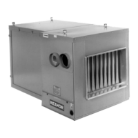
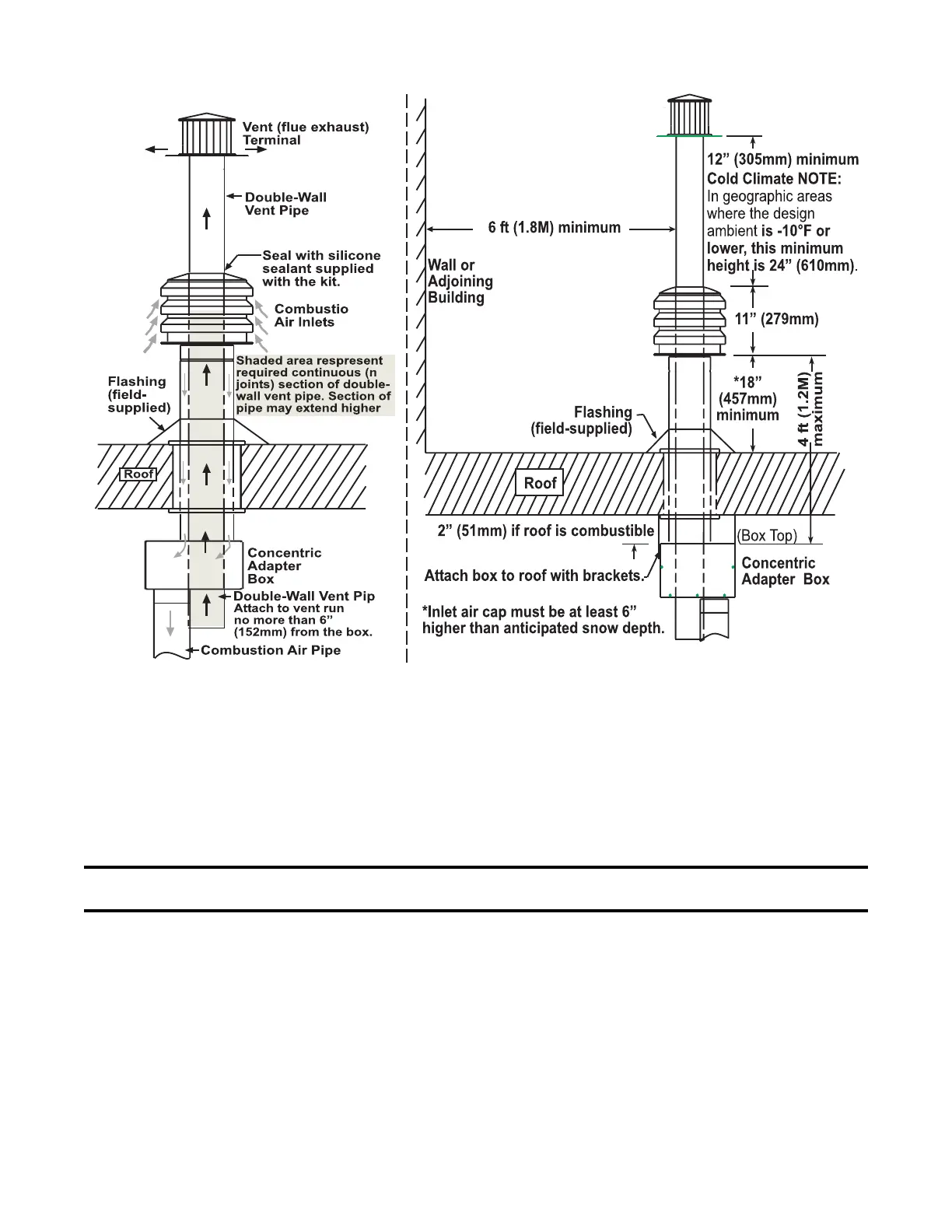
Figure 17. Option CC2 Installation
2. Install vent pipe and combustion air pipe runs:
a. Connect piping to heater in accordance with specifications listed above in Specific Venting Requirements:
Piping and Specific Venting Requirements: Venter Outlet and Combustion Air Inlet Connections.
b. Seal all joints in accordance with specifications listed above in Specific Venting Requirements: Joints and
Sealing. Due to high temperature considerations, do not enclose exhaust pipe or place pipe closer than 6
inches (152 mm) to combustible material.
c. Extend piping runs close to roof at location selected in step 1 and support piping in accordance with specifications
listed above in Specific Venting Requirements: Support.
NOTE: The larger diameter combustion air pipe serves as clearance for the vent pipe on non-
combustible construction.
3. Cut hole through outside wall for combustion air pipe.
a. Ensure that hole accommodates 8-inch (203-mm) combustion air pipe.
b. A thimble may be required depending on wall construction and/or local codes.
4. Connect concentric adapter box:
a. Refer to Figure 14 to attach brackets to box.
b. Refer to Figure 18 to connect outside portion of combustion air pipe to box. Determine length of combustion
air pipe so that dimension X in Figure 18 is equal to bracket length plus roof thickness and plus anticipated
snow depth. Ensure that length of combustion air pipe does not exceed 48 inches (1219 mm) or does not
extend less than 18 inches (457 mm) above roof.
c. Secure inlet air pipe to collar of concentric adapter box using sheet metal screws.
d. Insert combustion air pipe through roof as shown in Figure 18, DETAIL A
 Loading...