23
I-SCE (09-18) PN207697R9
• After all connections are made, disconnect the pilot supply at the control valve and bleed the system of all air.
Reconnect the pilot line and leak test all connections by brushing on a soap solution.
Sizing Gas Supply Lines
NOTE: When sizing supply lines, consider the possibility of future expansion and increased
requirements. Refer to National Fuel Gas Code for additional information on line sizing.
Sizing of gas supply lines depends on piping capacity and is based on the following:
• Cubic feet per hour based on a 0.3 IN WC pressure drop
• Specific gravity for natural gas: 0.6 (1000 BTU per cubic feet)
• Specific gravity for propane gas: 1.6 (2550 BTU per cubic feet)
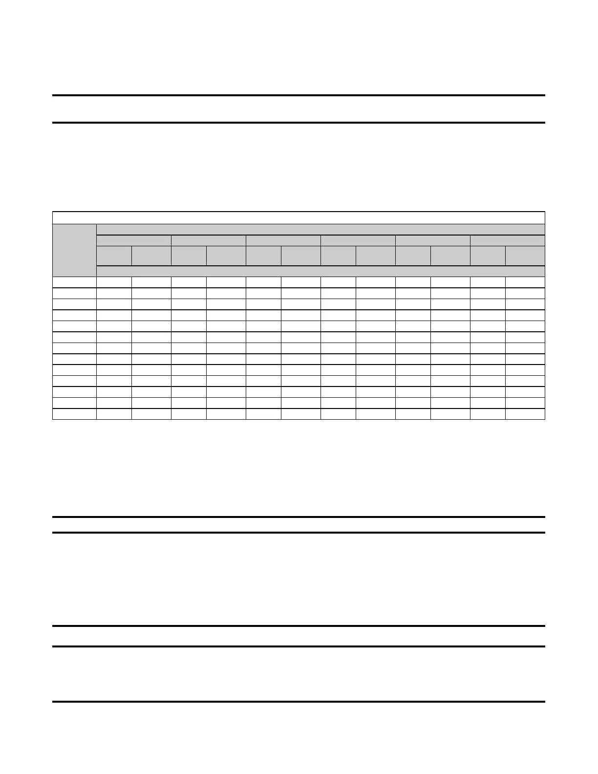
Variables for sizing gas supply lines are listed in Table 11.
Table 11. Gas Supply Line Sizes
Length
of Pipe
(Feet)
Diameter of Pipe (Inches)
1/2 3/4 1 1-1/4 1-1/2 2
Natural
Gas
Propane
Gas
Natural
Gas
Propane
Gas
Natural
Gas
Propane
Gas
Natural
Gas
Propane
Gas
Natural
Gas
Propane
Gas
Natural
Gas
Propane
Gas
Cubic Feet per Hour
20 92 56 190 116 350 214 730 445 1100 671 2100 1281
30 73 45 152 93 285 174 590 360 890 543 1650 1007
40 63 38 130 79 245 149 500 305 760 464 1450 885
50 56 34 115 70 215 131 440 268 670 409 1270 775
60 50 31 105 64 195 119 400 244 610 372 1105 674
70 46 28 96 59 180 110 370 226 560 342 1050 641
80 43 26 90 55 170 104 350 214 530 323 990 604
90 40 24 84 51 160 98 320 195 490 299 930 567
100 38 23 79 48 150 92 305 186 460 281 870 531
125 34 21 72 44 130 79 275 168 410 250 780 476
150 31 19 64 39 120 73 250 153 380 232 710 433
175 28 17 59 36 110 67 225 137 350 214 650 397
200 26 16 55 34 100 61 210 128 320 195 610 372
Manifold or Orifice (Valve Outlet) Pressure Settings
Measuring manifold gas pressure cannot be done until the heater is in operation (see Post-Startup Checklist). The
following warnings and instructions apply.
• For natural gas: When the heater leaves the factory, the combination valve is set so that the outlet gas pressure
of a single-stage valve or high fire of a two-stage valve is regulated to 3.5 IN WC. Low fire on a two-stage valve
is set to 1.8 IN WC. Inlet supply pressure to the valve must be a minimum of 5 IN WC or as noted on the rating
plate and a maximum of 14 IN WC.
NOTE: Always check the rating plate for minimum gas supply pressure.
• Minimum natural gas supply pressure: Requirements vary based on size of burner and the gas control option.
Most units require a minimum of 5 IN WC natural gas as stated above, but sizes 350 and 400 with electronic
modulation require a minimum of 6 IN WC natural gas supply pressure. Sizes 300 and 350 with mechanical
modulation require 7 IN WC.
• For propane gas: When the heater leaves the factory, the combination valve is set so that the outlet gas pressure
of a single-stage valve or high fire of a two-stage valve is 10 IN WC. Low fire on a two-stage valve is set to 5 IN
WC. Inlet pressure to the valve must be a minimum of 11 IN WC and a maximum of 14 IN WC.
⚠ WARNING ⚠
Before attempting to measure or adjust manifold gas pressure, the inlet (supply) pressure must be
within the specified range for the gas being used, both when the heater is in operation and when it
is on standby. Incorrect inlet pressure could cause excessive manifold gas pressure immediately
or at some future time.
 Loading...