31
UEZ-IOM (07-23) 1034347-I
Condensate Drain Installation
⚠ CAUTION ⚠
Apply general plumbing practices if pipe insulation or heat tapes are required to prevent freezing
of the condensate drain system.
• Because condensate is produced both in the heater and in the venting system, the installation requires a condensate
drain from the vent pipe and from the secondary heat exchanger.
• Condensate from the heater has a pH of 6 and is not harmful to a sanitary drain. Actual pH may vary ±1 depending
on fuel and combustion air.
• Unit sizes 055, 085, and 110 produce approximately 1/2 gallon (2 liters) of condensate per hour. Unit sizes 130 and
180 produce approximately 1 gallon (4 liters) of condensate per hour. Unit sizes 260 and 310 produce approximately
2 gallons (8 liters) of condensate per hour.
• A condensate disposal system that relies on gravity should be satisfactory for most installations as unit heaters
are normally installed several feet above the floor. If a gravity system is not possible, a condensate pump may
be installed. There are a number of commercially-available pumps made for this purpose. If using a condensate
pump, follow the pump manufacturer’s installation recommendations.
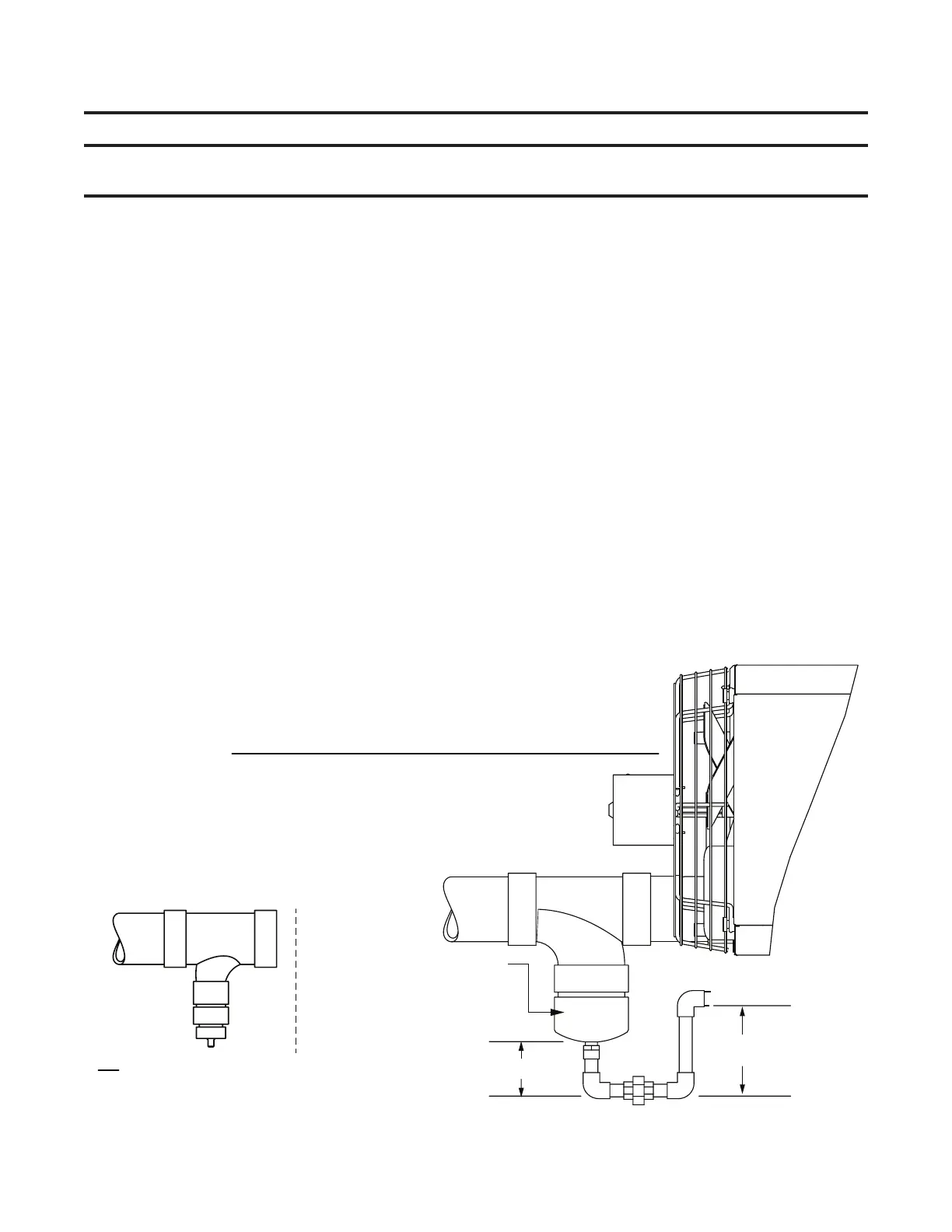
• The orientation of the piping is not critical and may be arranged to suit the installation. Unions are recommended
to permit maintenance of the drains and to facilitate service of the heater. A union is shown in both of the traps and
a third union is recommended in the drain pipe. If pipe insulation or heat tapes are required to prevent freezing,
use should be in accordance with general accepted plumbing practices.
• Each condensate drain must include a drain trap. Downstream from the traps, the condensate drains may be joined
and both must be connected to a common pipe that is connected to a sanitary drain within the building. Check
codes to ensure that this is permitted.
• The most important part of fabricating and assembling the drain traps is the length of the individual legs of the
traps. If the difference in the lengths of the legs of the traps are not as shown (see Figure 20 for vent drain trap or
Figure 21 for heat exchanger drain trap), it could prevent proper drainage of the condensate and possibly permit
vent gas to enter the building. Note that the length difference is also what provides a water seal to prevent the
leakage of vent gas into the sanitary drain.
Figure 20. Vent Condensate Drain Trap
C
D
Continue into
sanitary drain
Minimum Dimensions for Vent Pipe Condensate Drain Trap
C = to suit installation
D = C + at least 1-1/2 inches (38 mm)
Use 1/2-inch PVC pipe or larger for drain trap
4-inch PVC cleanout cap shown
is in vent/combustion air kit
(option CC6 or CC2)
Cap is drilled and tapped
for 1/2-inch NPT fitting
UNIT
Drain Trap
OR
Vent drain connection fittings may be field-supplied as shown
Drain must be 1/2-inch or larger
Trap requirements are same for either type of connection