9
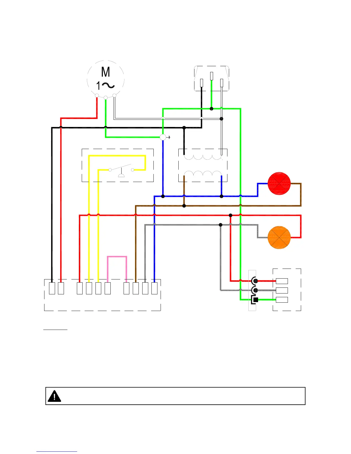
Figure 6. Internal Burner Wiring Diagram.
If any of the original wire as supplied with the appliance must be replaced, it must be replaced
with wiring material having a temperature rating of at least 220°F/105°C
LN
G
120V AC Fan
120V/60Hz AC
Supply
L1
Gas Control
MV
X
C
COM
W1
PS0
PS1
IND
R
Gas Valve
C
M
E
NOTES:-
Power On light is permanently illuminated when 120V / 60 Hz AC external supply is connected
to burner.
Additional wiring is required to install an optional extra thermostat and / or time clock.
If no thermostat is required then a jumper is fitted between terminals R and W1. In this
configuration the burner will continuously fire until the 120V power supply is disconnected.
Wire specification:- 18 AWG (1.0mm²), Tri-rated, 105°C
Pressure Switch
120v/24VAC 60Hz
Transformer
Power ON (red)
Burner ON (amber)
BK
R
Y
K
BR
GR
BL
KEY:
BL - BLUE
BK - BLACK
BR - BROWN
GR - GREY
G - GREEN
K - PINK
R - RED
W - WHITE
Y - YELLOW
K
Y
R
YY
R
W
G
BK
W
G
BL BR
RGR
R
GR
G
BR
BL
W
BK
G
E