15
VZ-VZH-VZT-IOM (08-24) 1047121-A
Table 5. Field-Installed Options
Option Description
CC1 Vent cap, 4- or 6-inch
CC17 Vent terminal, 4-inch, Tjernlund
CC26 Vent terminal kit
CD28 Reflector side extension kit
CK53 Steel hanger kit
CK55 Stainless steel hanger kit
CK54 Steel turnbuckle kit
CK56 Stainless steel turnbuckle kit
CL22 Thermostat, two-stage, digital
CL83 Thermostat, programmable, WIFI-enabled, 2H/2C
CM1 Thermostat guard with locking cover
DJ20 High-elevation conversion kit
DL2 Propane conversion kit (models VZ and VZH)
DN7 Protective grille kit
DO3 Protective (lower clearance) shield kit
IRT1 Transformer relay for multiple unit control
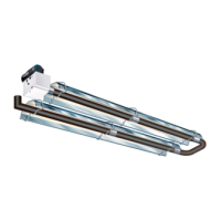
Tube Assembly
1. Align tubes on saw horses—burner tube and, if required, any extension tubes, U-tubes, and L-tubes. Ensure that
offset mounting hole on burner tube flange is on top and that weld seams are on bottom.
NOTE: Turbulators are NOT USED on the following units: model VZ and VZH unit sizes 125, 150,
175, and 200 and model VZT unit sizes 175 and 200.
2. Install turbulator(s) as required (refer to Table 6 for applicability and to Table 7 for quantity):
a. Interlock turbulator sections as shown in Figure 7 and slide assembly into extension tube. String may be used
as shown to position turbulator.
b. Fold tab around downstream end of tube as shown in Figure 7 to secure turbulator.
Table 6. Turbulator Applicability
Model
Unit Size (MBTUh)
40 60 80 100 115 125 140 150
Turbulator Location
VZ, VZH Burner tube
1st extension
tube
2nd extension
tube
—
3rd extension
tube
—
VZT —
1st extension
tube
2nd extension
tube
—
2nd extension
tube
—
3rd extension
tube
Table 7. Number of Turbulators Required
Model
Unit Size (MBTUh)
40 60 80 100 115 125 140 150
No. of Turbulator Connector Sections*
VZ
3**
4
4
1 3
—
1
—
VZH
2 — —
VZT — — 3 2
*Connector sections are connected to one (1) tabbed section.
**Installed as follows: from the exhaust end of the tube, one tabbed section, two connector sections, and one stainless steel connector
section.