33
VZ-VZH-VZT-IOM (08-24) 1047121-A
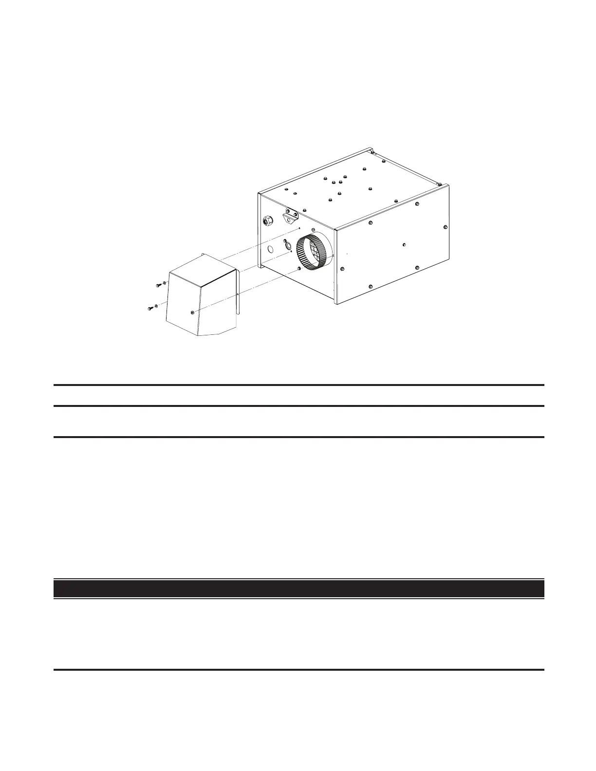
Figure 27. Combustion Air Inlet Hood Installation (Model VZH)
Piping Connections
⚠ CAUTION ⚠
Ensure that all high-pressure testing of the gas line is completed before connecting the gas supply
to the heater.
Gas Supply Pressure
• The unit is equipped for a maximum gas supply pressure of 1/2 psi, 3.5 kPa, or 14 IN WC for natural gas or propane.
The minimum supply pressure, as measured while the unit is operating at full fire, is 4.6 IN WC (unit sizes 40–150)
or 5 IN WC (unit sizes 175 and 200) for natural gas or 11 IN WC for propane.
• Supply pressure higher than 1/2 psi requires the installation of an additional service regulator external to the unit.
• Pressure testing supply piping: For test pressures above 1/2 psi, disconnect the heater and manual valve from
the gas supply line to be tested and cap or plug the supply line. For test pressures below 1/2 psi, before testing,
close the manual valve on the heater.
Gas Supply Piping
⚠ DANGER ⚠
• All components of a gas supply system must be leak tested prior to placing equipment in service.
NEVER TEST FOR LEAKS WITH AN OPEN FLAME. Failure to comply could result in personal
injury, property damage, or death.
• Pipe joint compounds (pipe dope) shall be resistant to the action of liquefied petroleum gas or
any other chemical constituents of the gas being supplied.
Installations That Do Not Require Outside Combustion Air
For model VZ and VZT installations that do not require outside combustion air, no alterations are needed. For model
VZH installations that do not require outside combustion air, install the combustion air inlet hood as follows:
1. Remove and save screws and nut shown in Figure 27.
2. Position combustion air inlet hood over flue collar as shown in Figure 27) and align flange holes.
3. Secure hood to burner cabinet using existing screws and nut.