30
VZ-VZH-VZT-IOM (08-24) 1047121-A
INSTALLATION—CONTINUED
Vent Connections—Continued
Common Venting
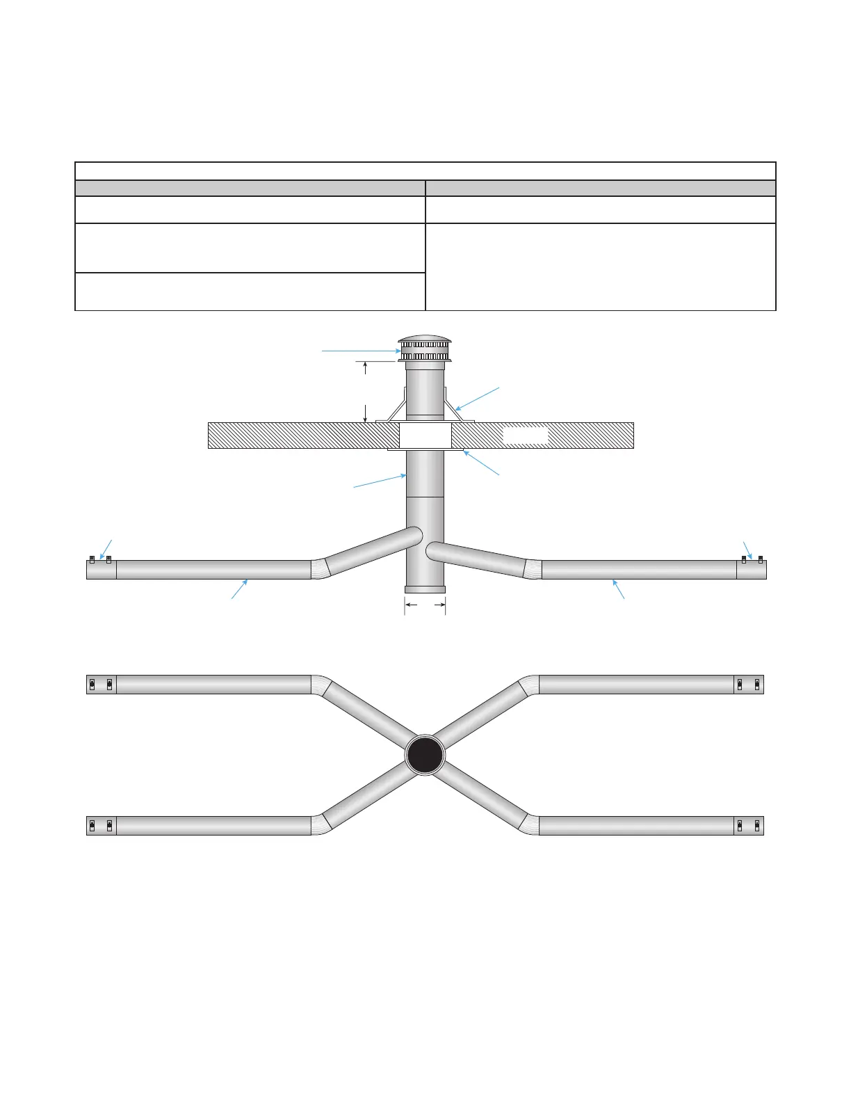
Figure 23. Category III Common Vertical Venting
SIDE VIEW
A
7- OR 8-INCH FIELD-SUPPLIED VENT CAP
ROOF FLASHING
ROOF
APPROVED THIMBLE
(IF APPLICABLE)
SINGLE-WALL
4-INCH SINGLE-WALL 4-INCH SINGLE-WALL
VENT ADAPTER VENT ADAPTER
24 INCHES
(MINIMUM)
Table 14. Common Venting Specifications
Vertical Horizontal
Maximum of four heaters with same BTU output and controlled by
common thermostat may be vented through roof
Maximum of two heaters with same BTU output and controlled by
common thermostat may be vented through side wall
Common stack connections must be positioned to avoid direct
opposition to combustion gas streams—area of common stack
dimension A (see Figure 23) must equal sum of open area of
individual vents
Continuous section of Type B vent pipe may be used only to pass
through outside wall or outside of building—not permitted to be used
inside space for Category III venting
Continuous section of Type B vent pipe may be used only to pass
through roof or outside of building—not permitted to be used inside
space for Category III venting