37
VZ-VZH-VZT-IOM (08-24) 1047121-A
Supply Wiring Connection
• Check the rating plate on the heater for the supply voltage and current requirements and ensure that all wiring is
in accordance with the wiring diagram provided with the unit.
• Run the supply wiring through the supply wiring entrance (see Figure 1, Figure 2, or Figure 3) and connect to the
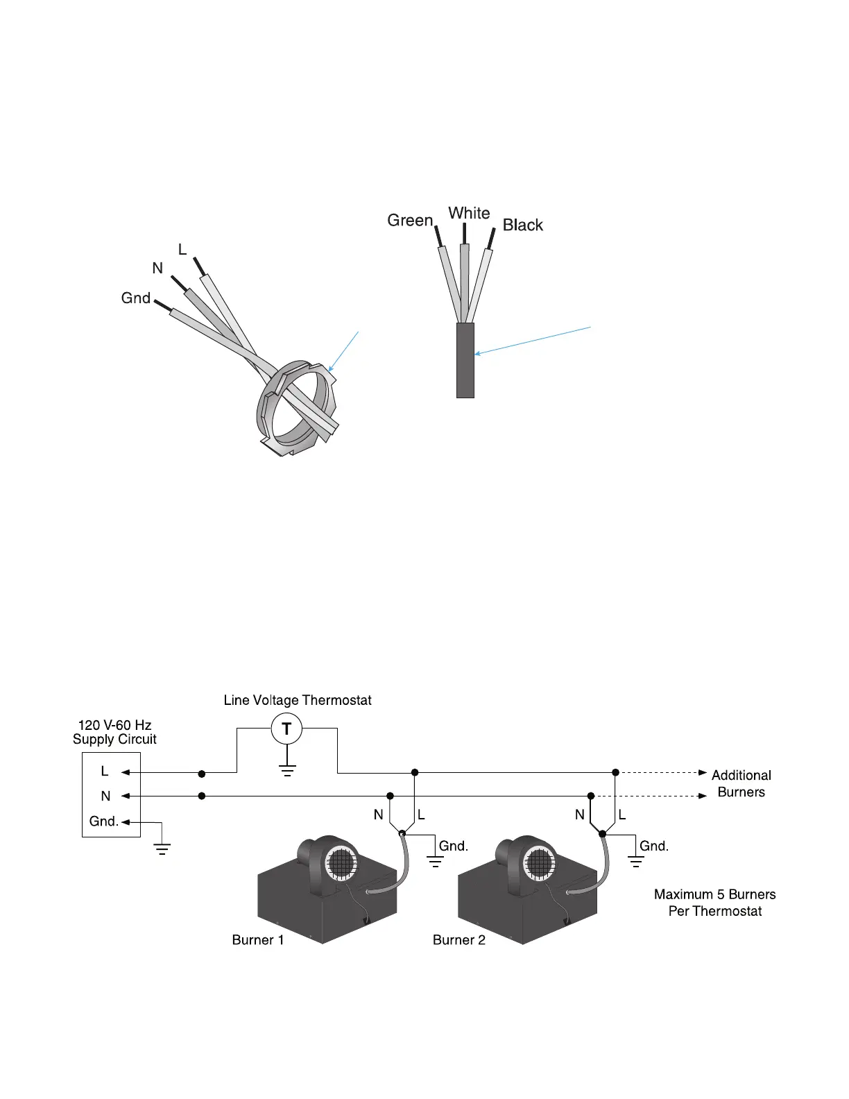
internal wire bundle using wire nuts—black (live) to L, white (neutral) to N, and green (ground) to Gnd—as shown
in Figure 30. Use a field-supplied BX or Romex connector for models VZ and VZT or field-supplied liquid-tight
conduit and conduit connector for model VZH.
Figure 30. Supply Wiring Connection
Control Wiring Connections
• Run any control wiring through the supply wiring entrance (see Figure 30) and connect using wire nuts. Ensure
that all wiring is in accordance with the wiring diagram provided with the unit.
• Line voltage thermostat: For models VZ and VZH, install the line voltage thermostat in accordance with the
thermostat manufacturer’s instructions and connect wiring in accordance with Figure 31 or Figure 32.
• Low voltage thermostat: Install the low voltage thermostat in accordance with the thermostat manufacturer’s
instructions. For model VZH, connect wiring in accordance with Figure 33. For model VZT, connect wiring in
accordance with Figure 34. For connecting multiple burner cabinets (up to eight), a separate transformer relay
(option IRT1) must be installed. Refer to the manufacturer’s installation instructions provided with the transformer
relay and to the wiring diagrams in the replacement parts manual found at www.reznorhvac.com.
SUPPLY
WIRING
ENTRANCE
Figure 31. Model VZ Line Voltage Thermostat Wiring