Form I-X, P/N 150491 R7, Page 14
6.0 Mechanical
(cont'd)
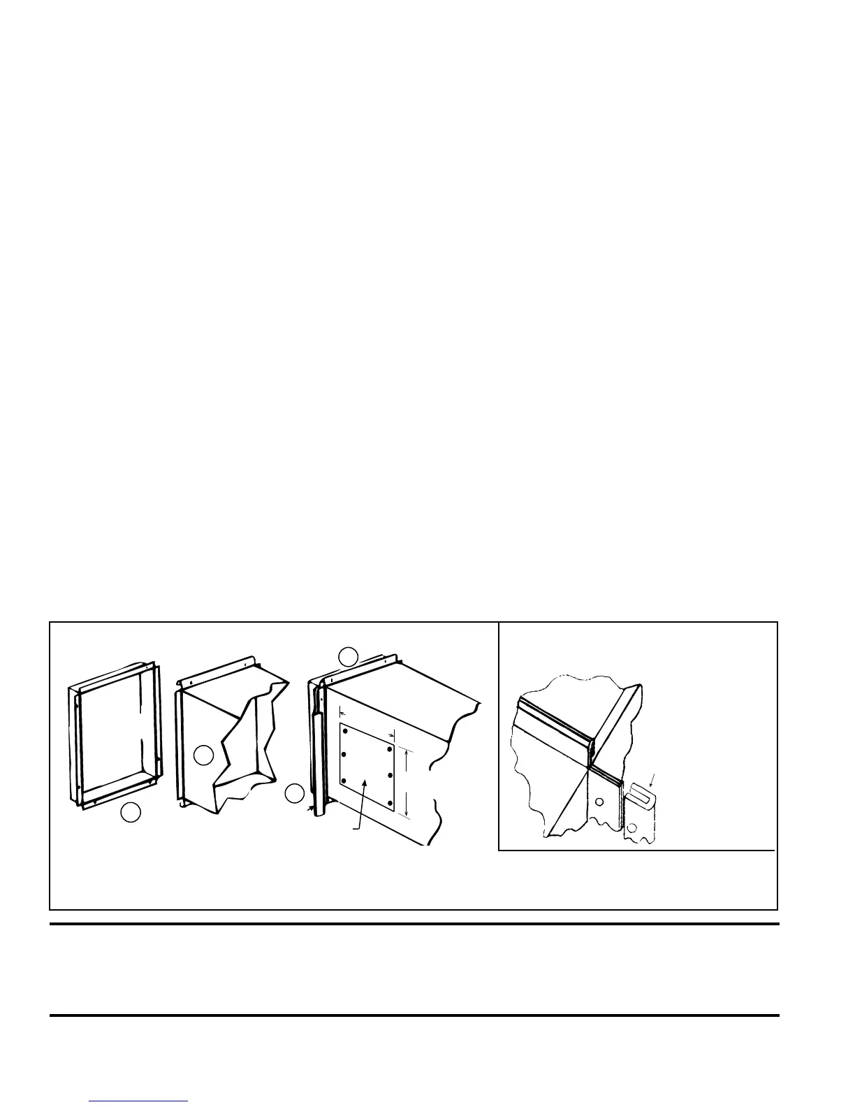
FIGURE 15 - Install "U" Channel
on Sides of Duct Connection
FIGURE 14 - Connecting Supply Air Duct to the Furnace
Heater
Duct
Access Panel in Duct
6
(152mm)
10 (254mm)
1
2
3
4
U
Channel
(1) Flanges on the furnace (heat exchanger) turn out as shown. (2) Shape duct connection as shown -- "U" on top
and bottom; "L" on sides. (3) Slide "U" channels over furnace top and bottom anges making connection. (4) Form "U"
channels to seal sides. Drill and lock with sheetmetal screws.
6.3 Duct Furnace
Airow (cont'd)
6.3.4 Duct Connections (cont'd)
CAUTION: Joints where ducts attach to furnace must be sealed securely to prevent
air leakage into drafthood or burner rack area. Leakage can cause poor combustion,
pilot problems, shorten heat exchanger life and cause poor performance. See Hazard
levels, Page 2.
• Through Masonry Walls - No warm air duct should come in contact with masonry
walls. Insulate around all air duct through masonry walls with not less than 1/2" (1"
is recommended) of insulation.
• Through Unheated Space - Insulate all exposed warm air ducts passing through
an unheated space with at least 1/2" (1" is recommended) of insulation.
• Duct Supports - Suspend all ducts securely from building members. Do not sup-
port ducts from unit duct connections.
• Duct Sizing - Proper sizing of the supply air ductwork is necessary to ensure a
satisfactory heating installation. The recognized authority for such information is
the Air Conditioning Contractors Association, 2800 Shirlington Road, Suite 300,
Arlington, VA 22206 (www.acca.org). A manual covering duct sizing in detail may
be purchased directly from them.
• Removable Panels - The ducts should have removable access panels on both
upstream and downstream sides of the furnace. These openings must be acces-
sible when the furnace is in service and should be a minimum of 6" x 10" in size
so smoke or reected light may be observed inside the casing to indicate the pres-
ence of leaks in the heat exchanger. The covers for the openings must be attached
in such a manner as to prevent leakage. See FIGURE 14.
• Horizontal Discharge Duct Length - A minimum horizontal duct run of 18"
(457mm) is required before turns or branches are made in the duct system to pre-
vent interference with the built-in drafthood..
• Supply Air Duct/Furnace Horizontal Connection - The seal between the fur-
nace and the duct must be mechanical. Duct connection should be made with "U"
type anges on the top and bottom of the connecting duct. Slide the duct over the
anges of the heater giving an airtight t. Provide "U" type channels for the other
side anges to ensure tight joints. Use sheetmetal screws to fasten ducts and "U"
channels to the furnace ange. See FIGURES 14 and 15.
• Return Air Duct/Furnace Connection - All return air ducts should be attached
and sealed to return air anges to provide airtight connection.
• Return Air Duct/Grill Size - Make certain that return air ducting or grills have a
free area equal to the return duct size connection.